In this article…
- Why a lighting layout calculator changes everything
- What is a lighting layout calculator? Definition, scope and use cases
- The lux method: core formula for every lighting layout calculator
- Room-by-room lighting layout calculator: targets, spacing and product recommendations
- Aluminium LED profiles vs plastic LED channels: the definitive comparison
- Selecting the right LED strip for each profile type
- Interactive lighting layout calculator tool: how to use it
- Lux targets by room type: EN 12464-1 and international standards
- Energy efficiency, power density and regulatory compliance
- The 5 steps of professional lighting design
- Sloped, vaulted and cathedral ceilings: special cases for the calculator
- Recessed lighting installation: technical guide for aluminium LED profiles
- Hotel and hospitality lighting: advanced layout planning with LED profiles
- Sustainability, circular economy and LED profile environmental performance
- Intelligent lighting, IoT and the future of the lighting layout calculator
- LightingLine.eu LED profile catalogue: key profile families
- The 10 most common lighting layout mistakes (and how the calculator prevents them)
- Professional lighting design software vs the lighting layout calculator
- Colour rendering, CCT and circadian impact: parameters beyond the lux calculator
- LED profile maintenance and long-term performance management
- Frequently asked questions: lighting layout calculator
- Market trends, industry research and the professional lighting designer’s outlook to 2030
- Appendix A: quick reference tables for the lighting layout calculator
- The lighting layout calculator as the foundation of every great lighting project
Why a lighting layout calculator changes everything
Lighting design has historically been treated as a finishing touch, something chosen from a catalogue after the structural and mechanical decisions were already locked in. The consequence of this attitude fills every commercial and residential space with glaring over-illumination in one zone, gloomy under-illumination in another, uncomfortable uniformity ratios, wasted energy and dissatisfied occupants. A lighting layout calculator reverses this approach entirely. It moves lighting decision-making to the earliest phase of interior design, where every lumen, every fixture position and every cable run can still be optimised without cost penalties.
The global LED lighting market was valued at approximately USD 75 billion in 2024 and is projected to reach USD 160 billion by 2030, growing at a CAGR of around 13.5% (Grand View Research, 2024). Within this market, LED strip lights and linear LED profiles account for the fastest-growing sub-segment, driven by architectural and hospitality applications that demand precise, continuous lines of light rather than point sources. Yet despite this growth, surveys consistently show that 60–70% of LED installations in the residential and light commercial sectors are not calculated before installation, they are estimated, often incorrectly, leading to returns, callbacks and costly re-installations.
The lighting layout calculator, whether implemented as a software tool, a web-based interactive calculator, a spreadsheet or the manual lux-method formula, is the professional’s answer to this endemic problem. In this article we build every calculation from first principles, room by room, and connect each calculation to real aluminium LED profiles and LED strip solutions from LightingLine.eu.
What is a lighting layout calculator? Definition, scope and use cases
A lighting layout calculator is any computational method, digital or manual, that translates a set of inputs (room dimensions, target illuminance, fixture photometry, surface reflectances and maintenance factors) into a concrete set of outputs: the number of fixtures required, their spacing, their aiming angles and the predicted uniformity ratio across the working plane. The term encompasses a spectrum of tools from a pencil-and-paper lux-method calculation to enterprise-grade photometric simulation software such as DIALux Evo or Relux.
Inputs to a lighting layout calculator
Every lighting layout calculator, regardless of sophistication, requires the same core set of inputs. Understanding these inputs is the prerequisite for using any tool intelligently:
- Room dimensions (length × width × height in metres): the geometric envelope determines both the area to be illuminated and the mounting height for fixtures.
- Target illuminance (lux, E): derived from the activity performed in the space, guided by EN 12464-1 (indoor lighting standard in Europe) or the IES Lighting Handbook (North America).
- Fixture photometry (luminous flux in lumens, beam angle in degrees, luminous intensity distribution): the photometric data file (IES or LDT format) characterises exactly how a fixture distributes light.
- Surface reflectances (ceiling ρc, walls ρw, floor ρf): reflected light is a significant contributor to illuminance, particularly in small rooms with light-coloured surfaces.
- Maintenance factor (MF): accounts for the inevitable depreciation of luminous flux over time due to lamp ageing, dirt accumulation on optics and surface soiling.
- Room Index (RI or k): a dimensionless ratio linking room geometry to the efficiency of light utilisation.
Outputs of the calculator
- Number of fixtures (N)
- Fixture spacing (S, in metres)
- Uniformity ratio (U₀ = Emin / Eavg, target ≥ 0.60 for general lighting per EN 12464-1)
- Power density (W/m²) for compliance with energy standards
- Estimated energy consumption (kWh/year)
LED profiles vs point sources: why the calculator differs
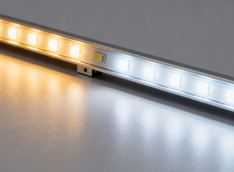
LED strip profiles and linear LED extrusions require a different calculation approach from point-source downlights. A linear source such as an LED strip installed in an aluminium profile distributes luminous flux along its entire length, creating a continuous luminous line rather than a cone. The key metric becomes luminous flux per metre (lm/m) rather than total lumen output per fixture. This means the lighting layout calculator must account for:
- the run length of the LED profile in the room;
- the mounting geometry (recessed into ceiling, surface-mounted, suspended, wall-mounted, under-cabinet);
- the beam angle of the diffuser (opal diffusers spread light at 120–160°; clear covers concentrate it);
- the spacing between LED strips within the profile (LED pitch affects hotspot uniformity).
When specifying continuous LED profiles for cove lighting, under-cabinet illumination, stair nosing, or facade washing, always request the photometric file per metre of run from the profile manufacturer.
The lux method: core formula for every lighting layout calculator
Before examining digital tools, every professional must understand the foundational formula that underpins every lighting layout calculator. This is the Lumen Method (also called the Average Illuminance Method or Utilisation Factor Method), the workhorse of photometric calculation since the 1940s, updated continuously by CIE and national standards bodies.
The fundamental lux equation
N = number of luminaires required
E = target illuminance (lux)
A = area of the working plane (m²)
Φ = luminous flux per luminaire (lumens)
UF = utilisation factor (from manufacturer tables, function of Room Index and reflectances)
MF = maintenance factor (typically 0.67–0.80 for LED)
This formula is the engine inside every lighting layout calculator free tool on the internet, every lighting calculator UK professional service, and every LED lighting calculator built into specification software. Mastering it manually gives you the ability to sanity-check any automated tool.
Calculating the room index (k)
L = room length (m)
W = room width (m)
Hm = mounting height above working plane (m)
The Room Index is the single most important geometric parameter in any lighting layout calculator. It determines the utilisation factor directly. A low Room Index (k < 1), typical of narrow corridors, hallways and under-cabinet spaces, means a large fraction of emitted light hits walls and is absorbed before reaching the working plane. A high Room Index (k > 3), typical of large open-plan offices or warehouses, means most light travels directly to the floor and is used efficiently.
| Room index (k) | Typical space | Approximate UF range (white room) | Recommended action |
|---|---|---|---|
| 0.5 – 0.8 | Narrow corridor, under-shelf | 0.25 – 0.40 | Use linear LED profiles with wide beam, maximise wall reflectance |
| 0.8 – 1.25 | Small bathroom, hallway, stairwell | 0.40 – 0.55 | Combine recessed downlights with cove LED strip for uniformity |
| 1.25 – 2.0 | Kitchen, bedroom, small office | 0.55 – 0.68 | Grid layout of downlights, LED profile perimeter cove for ambience |
| 2.0 – 3.0 | Living room, hotel lobby, classroom | 0.68 – 0.75 | Mixed system: linear LED profiles + downlights for task areas |
| 3.0 – 5.0 | Open office, retail floor, warehouse | 0.75 – 0.85 | High-efficiency LED linear battens in aluminium profiles, high-bay for >8m |
Maintenance factor (MF) for LED systems
The maintenance factor is often the most overlooked parameter in a lighting layout calculator. For LED systems, MF is the product of three sub-factors:
LLMF = Lamp Lumen Maintenance Factor (LED flux at end of design life / initial flux)
Typically 0.85–0.90 for quality LED at 50,000 h (L90 to L85 rating)
LSF = Lamp Survival Factor (probability of the LED being alive at end of design life)
Typically 0.95–0.99 for quality LED
LMF = Luminaire Maintenance Factor (effect of dirt on optics)
0.80 for clean enclosed profiles; 0.70 for open unprotected strips
This means a well-specified LED system in a clean aluminium profile with IP54 sealing achieves MF ≈ 0.90 × 0.98 × 0.85 = 0.75, while an unprotected bare LED strip in a dusty environment might drop to MF ≈ 0.80 × 0.90 × 0.70 = 0.50. The aluminium LED profile with a sealed diffuser effectively doubles the maintenance factor compared to an exposed plastic channel in a comparable environment.
Uniformity ratio (U₀)
Uniformity ratio is the ratio of minimum to average illuminance on the working plane:
General lighting in occupied zones: U₀ ≥ 0.40
Task lighting areas: U₀ ≥ 0.60
Display areas, fine work: U₀ ≥ 0.70
Achieving target uniformity is primarily a function of fixture spacing relative to mounting height. The classical rule: spacing-to-height ratio (SHR) should not exceed 1.5 for conventional luminaires, and should be around 1.0–1.2 for LED profiles with narrow optics.
Room-by-Room lighting layout calculator: targets, spacing and product recommendations
The most practical application of the lighting layout calculator is a room-by-room breakdown. Each space has its own activity profile, lux requirements, colour rendering demands, and aesthetic language. This section provides complete calculation examples for the most common room types, with specific aluminium LED profile and LED strip recommendations.
Kitchen lighting layout calculator
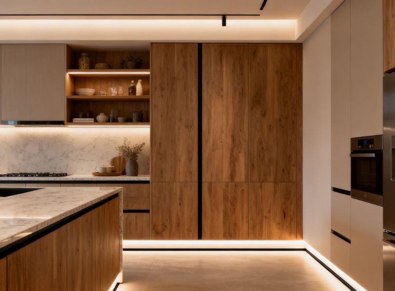
The kitchen is simultaneously the space with the highest lux demand (500–750 lux on worktops according to EN 12464-1) and the most diverse lighting zones: general ambient, task (worktop), feature (island or peninsula), accent (open shelving) and undercabinet. A proper kitchen lighting layout calculator must address all five zones independently before summing power loads.
Example calculation: 4.5 m × 3.0 m Kitchen, 2.6 m Ceiling Height
Mounting height Hm = 2.60 – 0.85 = 1.75 m
Room Index k = (4.5 × 3.0) / (1.75 × (4.5 + 3.0)) = 13.5 / 13.125 = 1.03Target illuminance:
General ambient: 300 lux (E₁)
Worktop task: 500 lux (E₂) — supplemented by undercabinet LED stripFixture: LED recessed downlight 6 inch, 1,100 lm, UF = 0.58 (k=1.03, ρc=0.7, ρw=0.5), MF = 0.75N (general) = (300 × 13.5) / (1,100 × 0.58 × 0.75) = 4,050 / 478.5 = 8.5 → 9 downlightsSpacing check: 4.5 m / 3 cols = 1.5 m; 3.0 m / 3 rows = 1.0 m
SHR = 1.5 / 1.75 = 0.86 ✓ (< 1.5, excellent uniformity)
For undercabinet task lighting, LED strips in aluminium profiles are the definitive solution. A 14 W/m LED strip (2,000 lm/m) mounted in a slim recessed aluminium profile under wall cabinets, with an opal diffuser, delivers approximately 800 lux on the worktop from 400 mm mounting height, well above the EN 12464-1 task requirement.
| Kitchen zone | Target lux | CRI minimum | CCT recommendation | Recommended solution |
|---|---|---|---|---|
| General ambient | 300 lux | Ra ≥ 80 | 3000–4000 K | Grid of LED recessed downlights |
| Worktop task | 500–750 lux | Ra ≥ 90 | 4000 K | LED strip in slim aluminium under-cabinet profile |
| Kitchen island | 500 lux | Ra ≥ 90 | 2700–3000 K | Pendant or suspended LED linear profile |
| Open shelving accent | 150–300 lux | Ra ≥ 90 | 2700 K | Micro LED strip in 8 mm aluminium profile |
| Plinth/kickboard | Decorative | Ra ≥ 80 | 2700 K | LED strip in flat aluminium plinth profile |
Living room lighting layout calculator
The living room requires the most nuanced approach of any residential space. Layered lighting (combining ambient, accent and decorative sources) is not merely aesthetic, it is photometrically necessary to achieve the wide range of illuminances required across a typical day: 50 lux for home cinema viewing, 150 lux for relaxed conversation, 300 lux for reading and 500 lux for hobby tasks. A lighting layout calculator for the living room must therefore accommodate dimming scenarios, not just a single fixed target.
Recommended living room lux targets by scene
| Scene | Target lux (MPHL*) | Dimming level | Primary source |
|---|---|---|---|
| Cinematic / media | 30–80 lux | 10–20% | Bias LED strip behind TV (aluminium wall profile) |
| Relaxed ambience | 100–200 lux | 30–50% | Cove LED profile + floor lamps |
| Social gathering | 200–300 lux | 60–80% | Recessed downlights + cove |
| Reading / hobbies | 300–500 lux | 80–100% | Task lamp + full ambient |
*MPHL = Mean Plane Horizontal Luminance, measured at 0.85 m above floor
For living room cove lighting, one of the most popular architectural LED applications, an aluminium recessed cove profile mounted at the ceiling perimeter creates a seamless luminous boundary. Using a 10 W/m LED strip (1,400 lm/m) in a 12 m perimeter room delivers approximately 16,800 lm of indirect ambient light, which after reflection factors equates to roughly 120–180 lux ambient, perfect for the relaxed ambience scene.
Bathroom lighting layout calculator
Bathroom lighting is governed by both photometric requirements and electrical safety zones defined by IEC 60364-7-701 (BS 7671 in the UK). The lighting layout calculator for bathrooms must integrate IP ratings into the fixture selection before any photometric calculation begins.
| Safety zone | Definition | Minimum IP rating | LED profile suitability |
|---|---|---|---|
| Zone 0 | Inside bath/shower basin | IP68 | IP68 LED strip in waterproof aluminium profile (silicone-filled) |
| Zone 1 | Above bath/shower to 2.25 m | IP45 | IP54 or IP65 recessed aluminium profile |
| Zone 2 | 600 mm outside Zone 1 | IP44 | Standard recessed or surface-mount aluminium profile IP44 |
| Outside zones | Rest of bathroom | IP20 | All standard aluminium profiles applicable |
Mirror lighting is the critical task zone in any bathroom. The EN 12464-1 standard recommends 500 lux at the face when seated, measured in the vertical plane. A LED mirror profile (vertical aluminium channel mounted either side of the mirror, each containing a 14 W/m 2,700 K Ra≥90 LED strip) delivers bilateral, shadow-free facial illumination far superior to a single overhead fitting. This is the professional specification used in hotels and high-end residential projects.
Bedroom lighting layout calculator
Bedrooms demand the lowest general ambient illuminance of any residential room, 100–150 lux for general use, falling to 50 lux or below for reading in bed (which relies on bedside task lamps). The lighting layout calculator for bedrooms focuses heavily on circadian compatibility: warm white (2700–3000 K), minimal blue-light content, and dimming capability to 1% or below for sleep preparation.
Recommended bedroom LED profile applications
- Headboard cove: aluminium surface-mount or wall-recessed profile with warm-white 2700 K LED strip, dimmable to 1% via Casambi or Lutron wireless control.
- Floating bed base: flat aluminium plinth profile concealed in the bed frame base, 2700 K, 3–5 W/m for gentle floor wash.
- Wardrobe interior: slim aluminium profile with PIR-triggered LED strip (500–700 lm/m) on each wardrobe shelf edge.
- Sloped ceiling niches: flexible aluminium profile or angled-mount recessed profile to follow raked ceiling geometry.
For bedrooms with vaulted ceilings or sloped ceiling lighting, standard recessed downlights require adjustable-angle bezels to avoid glare. An alternative, and often superior, approach is a continuous LED strip in a surface-mount aluminium profile installed along the ridge of the vault, providing indirect uplighting that emphasises the architectural form while delivering 80–120 lux general ambient.
Office & workspace lighting layout calculator
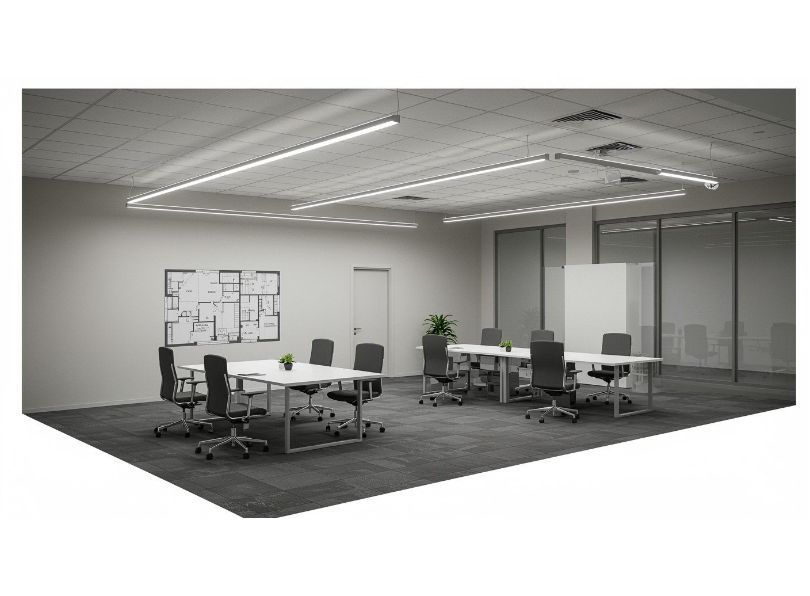
Office lighting is the most standards-regulated domestic or commercial lighting application. EN 12464-1 mandates 500 lux at the desk working plane for general office tasks, with a uniformity ratio U₀ ≥ 0.60 and a UGR (Unified Glare Rating) ≤ 19. These three requirements (lux, uniformity and glare) must all be satisfied simultaneously, which is why the lighting layout calculator is absolutely indispensable for office design.
Office lighting layout calculator example: 8 m × 6 m open office, 2.85 m ceiling
Hm = 2.85 – 0.75 = 2.10 m
k = (8 × 6) / (2.10 × (8 + 6)) = 48 / 29.4 = 1.63Target: 500 lux, UGR ≤ 19, U₀ ≥ 0.60Fixture: LED linear panel 1200 mm, 3,600 lm, UGR 16, UF = 0.65 (k=1.63), MF = 0.75N = (500 × 48) / (3,600 × 0.65 × 0.75) = 24,000 / 1,755 = 13.7 → 14 fixturesArrangement: 2 rows × 7 fixtures (1.2 m long each)
Row spacing: 6 / 3 = 2.0 m; Fixture spacing along row: 8 / 7 = 1.14 m (continuous run)
SHR along: 1.14 / 2.10 = 0.54 ✓ (excellent)
SHR across: 2.0 / 2.10 = 0.95 ✓
Linear aluminium LED profiles in suspended or recessed installations are the professional specification for office lighting. The profile not only provides the UGR-controlled diffuser essential for comfort, but also acts as a heat sink, extending LED lifespan to 50,000 h and maintaining lumen output above L90 throughout the maintenance period. This translates directly to a higher maintenance factor and a reduced number of fixtures required, a genuine whole-life cost advantage over bare LED tube fittings or plastic channel LED strips.
Workshop lighting layout calculator
Workshop and garage lighting has unique requirements: high lux levels (500–750 lux for fine mechanical work), excellent colour rendering (Ra ≥ 80, preferably ≥ 90 for paint mixing or detailed inspection), uniformity U₀ ≥ 0.50, and, critically, robust IP-rated fittings that can withstand vibration, dust and occasional chemical splash.
Workshop lighting layout calculator
Hm = 2.5 – 0.85 = 1.65 m
k = (6 × 4) / (1.65 × (6 + 4)) = 24 / 16.5 = 1.45Target: 500 lux, Ra ≥ 80, IP65Fixture: LED batten 1200 mm IP65, 4,000 lm, UF = 0.62, MF = 0.72 (IP65, dusty environment)N = (500 × 24) / (4,000 × 0.62 × 0.72) = 12,000 / 1,785.6 = 6.7 → 8 battensArrangement: 2 rows × 4 battens
Spacing: 4 / 2 = 2.0 m across; 6 / 4 = 1.5 m along
SHR = 2.0 / 1.65 = 1.21 ✓; 1.5 / 1.65 = 0.91 ✓
For workshops and garages, anodised aluminium LED profiles with IP65 polycarbonate diffusers represent the ideal solution. The aluminium extrusion provides superior heat dissipation in environments where ambient temperatures can reach 35–40°C, maintains lumen output within 5% of initial values throughout the design life, and resists the chemical cleaning agents routinely used in workshop environments. Plastic channels, by contrast, discolour, crack and distort under UV and solvent exposure, typically within 2–3 years.
High bay lighting layout calculator
For spaces with ceiling heights exceeding 6 metres (warehouses, factories, sports halls, aircraft hangars) the high bay lighting layout calculator introduces additional complexity: beam angle becomes critical, illuminance uniformity at floor level must be maintained from a great height, and emergency lighting autonomy requirements become more demanding.
| Ceiling height (m) | Recommended fixture type | Beam angle | Target lux (industrial) | Grid spacing (m) |
|---|---|---|---|---|
| 4 – 6 m | LED linear low-bay in aluminium profile | 90–120° | 300–500 lux | 3.0 – 4.0 m |
| 6 – 9 m | LED high-bay pendant, 100–200 W | 60–90° | 300–500 lux | 4.0 – 6.0 m |
| 9 – 14 m | LED high-bay 200–300 W | 45–60° | 200–500 lux | 6.0 – 8.0 m |
| > 14 m | LED high-mast floodlight or stadium LED | Asymmetric | 200–300 lux | 8.0 – 12.0 m |
Hallway & corridor lighting layout calculator
Hallways and corridors present one of the lowest Room Index scenarios in any building, narrow widths relative to ceiling heights produce k values below 0.8, meaning utilisation factors are poor and more fixtures are required per unit area than in any other space. The lighting layout calculator must compensate by either increasing fixture lumen output, reducing spacing, or switching to linear LED profiles that distribute light more efficiently along the corridor axis.
The professional recommendation for corridors is a continuous LED strip in a recessed aluminium profile running the full length of the corridor, centred in the ceiling. This approach:
- maximises utilisation factor for narrow rooms (linear sources parallel to corridor length);
- eliminates the multiple-downlight grid that creates scalloping on walls;
- permits integration of emergency lighting within the same profile run;
- creates an architecturally superior luminous line that visually extends the corridor.
For a 1.2 m wide corridor with 2.5 m ceiling, a single recessed aluminium profile containing a 10 W/m LED strip (1,400 lm/m) delivers approximately 300 lux at floor level — meeting the EN 12464-1 requirement of 100 lux minimum for corridors, with ample uniformity margin.
Aluminium LED profiles vs plastic LED channels: the definitive comparison for every application
The choice between aluminium LED profiles and plastic LED channels is one of the most consequential decisions in any LED lighting installation. It affects thermal performance, optical quality, maintenance factor, mechanical robustness, fire behaviour, environmental credentials and total cost of ownership over a 10–15 year design life. This section provides the most thorough, evidence-based comparison available, structured room by room and application by application.
Thermal performance: the critical difference
LED junction temperature is the primary determinant of LED lifespan, lumen maintenance and colour stability. Every degree Celsius reduction in junction temperature extends L70 lifespan by approximately 3–5%. Aluminium has a thermal conductivity of 160–205 W/m·K; the best polycarbonate plastic has a thermal conductivity of 0.19–0.22 W/m·K, a factor of approximately 800 times lower.
What does this mean in practice? A 14 W/m LED strip mounted in an aluminium profile running at an ambient temperature of 25°C will reach a junction temperature of approximately 55–65°C, maintaining L90 for 50,000 hours. The same strip in a plastic channel at the same ambient will reach 75–85°C junction temperature, reducing expected L70 lifespan from 50,000 to 20,000–25,000 hours, and causing irreversible colour shift (typically a warm yellow drift) within 15,000–20,000 hours.
| Parameter | Aluminium LED profile | Plastic (PVC/PC) LED channel |
|---|---|---|
| Thermal conductivity | 160–205 W/m·K | 0.19–0.22 W/m·K |
| Typical junction temperature (14 W/m, 25°C ambient) | 55–65°C | 75–85°C |
| Expected L90 lifespan | 50,000 h | 15,000–25,000 h |
| Colour shift after 20,000 h | < 3 SDCM (MacAdam steps) | 5–8 SDCM (visible yellowing) |
| Lumen maintenance at 30,000 h | ≥ 90% (L90) | 70–80% (L80 or below) |
| Maintenance factor implication | MF = 0.75–0.80 | MF = 0.55–0.65 |
Optical performance and diffuser quality
The diffuser in an LED profile serves two functions: it hides the LED source dots (eliminating hotspots) and it controls the beam angle. Aluminium profiles accept precision-extruded PMMA (acrylic) or polycarbonate diffusers that are manufactured to tight optical tolerances, providing consistent beam control and high light transmission (typically 88–92%). Plastic channels use integral diffusers moulded with much less precision, leading to:
- variable light transmission (70–82%): 6–18% more light is wasted in plastic channels;
- greater LED hotspot visibility, particularly with low LED density strips;
- UV degradation of the diffuser material: polystyrene channels yellow within 3–5 years under LED irradiance, permanently reducing transmission and creating a warm colour cast.
Room-by-room comparison: plastic channel vs aluminium profile
Kitchen: under-cabinet lighting
Under-cabinet lighting is one of the highest-use LED applications: potentially 8–12 hours per day, in a warm and humid environment with cooking vapours and occasional steam. Plastic channels in kitchens have a documented failure rate due to warping from heat, discolouration from cooking vapours and adhesive tape failure on smooth lacquered cabinet undersides. Aluminium profiles with a snap-fit mounting system provide secure mechanical fixing, thermal stability and a clean aesthetic that matches contemporary kitchen hardware.
| Feature | Plastic channel (kitchen) | Aluminium profile (kitchen) |
|---|---|---|
| Thermal stability at 40°C ambient | Begins to soften and warp, adhesive fails | Full dimensional stability, mechanical fixings secure |
| Vapour resistance | Porous material absorbs grease vapour | Anodised aluminium: non-porous, cleanable |
| Lifespan in kitchen environment | 3–5 years before replacement | 15–20 years with LED strip replacement only |
| Diffuser clarity after 5 years | Yellowed, 15–25% transmission loss | Clear PMMA diffuser, <5% transmission change |
| Aesthetic | Visible plastic body, consumer grade | Slim brushed aluminium, architectural grade |
| Product recommendation | — | Slim under-cabinet recessed aluminium profile |
Bathroom: mirror and zone lighting
In bathroom applications, the IP rating of the profile body is as important as the thermal performance. Plastic channels have no inherent IP rating; moisture ingress is common within 6–12 months, leading to corrosion of the LED strip PCB copper traces and premature failure. Aluminium profiles with IP44 or IP65 ratings (sealed diffuser gaskets, end caps) provide genuine moisture protection and comply with IEC 60364-7-701 zone requirements.
| Feature | Plastic channel (bathroom) | Aluminium profile (bathroom) |
|---|---|---|
| IP rating | IP20 (unrated plastic), zone compliance impossible | IP44–IP65 rated options for all bathroom zones |
| Moisture resistance | Moisture ingress within 12 months | Sealed profile, rated for Zone 2 use |
| Mirror profile option | Not available | Dedicated mirror aluminium profile, bilateral lighting |
| Compliance | Non-compliant in Zones 0, 1, 2 | Zone-specific rated profiles available |
| Product recommendation | — | IP65 bathroom and mirror aluminium profile range |
Living room: cove and pelmet lighting
Cove lighting is among the most photogenically sensitive LED applications: the slightest hotspot, colour inconsistency or diffuser yellowing is immediately visible against a plain white ceiling. Plastic channels produce visible LED hotspots at spacing above 50 mm between LEDs, require minimum 60 mm viewing distance to eliminate dots, and create visible jointing marks at channel connections. Aluminium profiles with optimised diffuser height ratios eliminate all visible hotspots at viewing distances above 300 mm from any angle.
| Feature | Plastic channel (cove) | Aluminium profile (cove) |
|---|---|---|
| Hotspot elimination | Requires <50 mm LED spacing or multiple diffuser layers | Optimised diffuser geometry eliminates hotspots at 60 LED/m or above |
| Jointing appearance | Visible join lines at channel ends | Precision-cut ends, invisible butt joints with connector clips |
| Beam control | Fixed 120° only (moulded diffuser) | Multiple diffuser options: 30°, 60°, 90°, 120°, opal flood |
| Recessed cove option | Not available (surface mount only) | Recessed plasterboard profile for flush-to-ceiling installation |
| Product recommendation | — | Recessed cove aluminium profile for plasterboard |
Staircase: stair nosing and wall recessed step lighting
Stair nosing LED profiles are a highly safety-critical application. BS 8300 (UK) and DIN 18040 (Germany) specify minimum illuminance of 150 lux on stair treads; EN 1838 specifies 1 lux minimum on escape routes. Plastic channels have no structural resistance to foot traffic and cannot be used in stair nosing applications — a loaded footfall applies point forces of 2–5 kN/m², which will crack any consumer plastic channel immediately. Anodised aluminium stair nosing profiles are designed and tested to withstand dynamic loads of 5–10 kN/m², conform to anti-slip surface requirements and serve as both the lighting element and the safety nosing in a single product.
| Feature | Plastic channel (stairs) | Aluminium stair nosing profile |
|---|---|---|
| Structural load capacity | 0 kN/m² (foot traffic will crack) | 5–10 kN/m² (traffic-rated) |
| Anti-slip surface | Not applicable | Integral anti-slip EPDM or carborundum insert |
| Dual function | None | Safety nosing + LED illumination in one profile |
| Compliance | Non-compliant for public stairways | Compliant with EN 14411, BS 8300 |
| Product recommendation | — | LED stair nosing aluminium profiles |
Outdoor/façade: soffit and perimeter LED lighting
Soffit lighting, facade washing and perimeter LED lighting for building exteriors demand IP65 minimum, UV resistance and resistance to thermal cycling between −20°C and +60°C. No plastic channel product is rated for outdoor use. Aluminium profiles with anodised or powder-coated finishes and UV-stable PC diffusers are the only suitable solution:
- anodised aluminium: corrosion resistance class C5 (EN ISO 12944), suitable for coastal environments
- thermal cycling resistance: aluminium expands/contracts predictably; profiles include expansion joints at 2 m intervals for runs above 5 m
- UV-stable PC diffusers: rated for 10 years outdoor UV exposure without yellowing
Summary comparison table: all applications
| Application | Plastic channel rating | Aluminium profile rating | Recommended profile |
|---|---|---|---|
| Kitchen under-cabinet | ⚠ Marginal (3–5 yr life) | ✅ Excellent | Slim under-cabinet profile |
| Bathroom mirror | ❌ Not compliant | ✅ IP44–IP65 rated | Mirror / bathroom IP profile |
| Living room cove | ⚠ Consumer grade only | ✅ Architectural grade | Recessed plasterboard cove profile |
| Stair nosing | ❌ Structurally unsafe | ✅ Traffic-rated | Stair nosing profile |
| Outdoor soffit | ❌ Not rated outdoor | ✅ IP65, UV stable | Outdoor soffit profile |
| Office linear | ⚠ No UGR control | ✅ UGR≤19 diffusers available | Suspended office linear profile |
| Retail display | ⚠ Poor optics | ✅ Narrow beam, accent control | Retail narrow-beam profile |
| Furniture / wardrobe | ✅ Acceptable (dry interior) | ✅ Superior (longer life) | Mini furniture profile 8mm |
Selecting the right LED strip for each profile type
The LED profile is only half of the system; the LED strip inside it determines the photometric output, colour quality, dimmability and energy consumption. A poorly matched LED strip in an excellent aluminium profile will underperform, a premium LED strip in the correct aluminium profile delivers system performance that far exceeds the sum of its parts. This section guides the selection process for each major profile category.
LED strip specifications: the parameters that matter
| Parameter | Definition | Typical range | Selection guidance |
|---|---|---|---|
| Power density (W/m) | Watt consumption per metre of strip | 4.8 – 24 W/m | Higher W/m = more lumens, match to profile thermal rating |
| Lumen output (lm/m) | Luminous flux per metre | 400 – 2,400 lm/m | Calculate from lux formula, allow for MF in aluminium profile |
| LED density (LED/m) | Number of LED packages per metre | 30 – 240 LED/m | Higher density = better uniformity, 60/m minimum for cove |
| CRI (Ra) | Colour rendering index | Ra 70 – Ra 98 | Ra≥80 for general, Ra≥90 for kitchens, retail, healthcare |
| CCT (K) | Correlated colour temperature | 2700 – 6500 K | 2700–3000 K residential, 4000 K office/kitchen; tunable-white ideal |
| Voltage (V) | Operating voltage | 12 V, 24 V, 48 V | 24 V for runs >5 m, 48 V for long architectural runs >10 m |
| IP rating | Protection against dust/moisture | IP20, IP44, IP65, IP68 | Match to installation zone requirements |
| CRI R9 | Red saturation rendering | 0 – 96 | R9 > 50 for food display, artwork, healthcare, R9 > 90 premium |
High-output LED strips: when and why
For applications requiring 500 lux or above from a single profile run (task lighting, retail display, workshop illumination) high-output LED strips (14–24 W/m, 1,800–2,400 lm/m) are essential. These strips generate significant heat and absolutely require aluminium profiles rated for their power density. The relationship between strip power density and required profile thermal resistance (R_th) is:
In aluminium profile (R_th ≈ 2.5 K/W·m): T_j ≈ 25 + (20 × 2.5) = 75°C — acceptable
In plastic channel (R_th ≈ 25 K/W·m): T_j ≈ 25 + (20 × 25) = 525°C — catastrophic failure
This calculation demonstrates why high-output LED strips must never be installed in plastic channels. Beyond the dramatic reduction in lifespan and lumen maintenance, there is a genuine fire risk at power densities above 10 W/m in unrated plastic enclosures. Browse high-output LED strip solutions at catalogue.lightingline.eu.
Tunable white LED strips in aluminium profiles
Tunable white (TW) LED strips (capable of adjusting CCT from 2700 K to 6500 K) are increasingly specified in healthcare, hospitality, education and high-end residential projects to support circadian rhythm alignment and scene flexibility. In aluminium profiles, TW strips require careful thermal management because dual-channel PWM dimming at high frequencies can create additional switching losses. Profiles with enhanced thermal mass (thicker baseplate) are recommended for TW applications above 10 W/m.
Interactive lighting layout calculator tool: how to use it and what it calculates
A web-based interactive calculator tool for lighting layout combines the lux method, room index calculation and fixture spacing optimisation into a single user interface. When evaluating or building such a tool, understanding its internal logic ensures you can interpret its outputs correctly and override its defaults when project conditions demand it.
Step-by-step: how to use an LED lighting layout calculator
- Enter room dimensions (length, width, ceiling height in metres or feet). The calculator derives floor area and room index automatically;
- Select room type from a dropdown, the calculator loads the EN 12464-1 or IES-recommended lux target for that room type. Advanced tools allow manual lux override;
- Select or input fixture data lumens per fixture (or lm/m for linear sources), beam angle, UGR rating, CRI. For LED profiles, input lm/m and profile type;
- Enter reflectances ceiling, wall, floor. Many tools default to 0.7/0.5/0.2 (white/mid/dark); override for specific finishes;
- Set maintenance factor 0.80 for clean aluminium-profile installations; 0.67 for open or dusty environments;
- Review outputs: number of fixtures, spacing grid, uniformity ratio, power density (W/m²), annual energy consumption estimate;
- Check against standards: verify U₀ ≥ 0.40 (general) or 0.60 (task), UGR ≤ 19 (office), power density ≤ regulatory limit (e.g. 10 W/m² for offices under EU EPBD);
- Iterate: adjust fixture type, quantity or spacing until all criteria are met simultaneously.
The spacing calculation for LED profiles
For recessed linear LED profiles in a ceiling grid, the spacing between parallel profile runs is calculated as
For direct-lit profiles (narrow diffuser): SHR_max = 1.0
For direct/indirect profiles: SHR_max = 1.2
For wide-flood diffuser profiles (≥120°): SHR_max = 1.5Example: 2.85 m ceiling, working plane 0.75 m, Hm = 2.10 m
Narrow profile: S_max = 1.0 × 2.10 = 2.10 m between profile runs
Wide flood: S_max = 1.5 × 2.10 = 3.15 m between profile runs
Downlight spacing calculator
For recessed spot lights and downlights, whether LED can lights, wafer lights or recessed ceiling lights, the primary spacing rule is
Spacing between fixtures: S_interior = HWhere H = floor-to-ceiling heightExample: 2.6 m ceiling
First row from wall: 2.6 / 2 = 1.30 m
Between fixtures: 2.6 / 1 = 2.60 m (maximum; reduce for higher lux)
For kitchens and areas with worktops, the first row of downlights should be positioned to illuminate the worktop edge — typically 600–750 mm in from the wall, not 1.3 m. This is the most common layout error caught by a proper kitchen lighting layout calculator.
Lux targets by room type: EN 12464-1 and international standards
The lux targets used in any lighting layout calculator must be grounded in recognised standards. EN 12464-1:2021 (Light and lighting, lighting of work places, part 1: indoor work places) is the primary reference standard for all commercial and residential projects in the EU and UK. North American projects reference the IES Lighting Handbook, 10th Edition. The following table consolidates the most referenced values:
| Space / activity | Maintained illuminance em (lux) | UGR max | CRI min (Ra) | Note |
|---|---|---|---|---|
| Residential — General areas | 100 | — | 80 | Living room background |
| Residential — Reading / hobby | 300 | — | 80 | Task lamp supplementary |
| Kitchen — General | 300 | 22 | 80 | Ambient layer |
| Kitchen — Worktop task | 500 | 22 | 80 | Under-cabinet LED profile |
| Bathroom — General | 200 | 25 | 80 | — |
| Bathroom — Mirror task | 500 (vertical) | — | 90 | Bilateral mirror profile |
| Office — General | 500 | 19 | 80 | VDU task included |
| Conference room | 500 | 19 | 80 | — |
| Reception / lobby | 300 | 22 | 80 | — |
| Corridor / passage | 100 | 28 | 40 | Safety lighting priority |
| Staircase | 150 | 25 | 40 | Tread illuminance critical |
| Classroom — Teaching | 500 | 19 | 80 | Vertical board: 500 lux |
| Retail — General | 300 | 22 | 80 | — |
| Retail — Display | 750–1,500 | — | 90 | Accent + general combined |
| Workshop — Coarse work | 300 | 25 | 80 | — |
| Workshop — Fine work | 500 | 22 | 80 | — |
| Workshop — Very fine work | 1,000 | 19 | 90 | Inspection bench |
| Car park / garage | 75 | 28 | 40 | — |
| Hotel — Bedroom | 100 | 19 | 80 | General; 300 at dressing table |
| Hospital — Ward | 100 | 19 | 80 | General; 300 reading; 1000 examination |
Energy efficiency, power density and regulatory compliance
A lighting layout calculator that optimises for lux and uniformity but ignores energy consumption delivers an incomplete result in 2025. The EU Energy Performance of Buildings Directive (EPBD) recast, EN 15193-1 (energy performance of buildings, energy requirements for lighting), and national building regulations (Part L in England and Wales, BSEN 15193 across Europe) all impose maximum Lighting Power Density (LPD) limits that must be satisfied alongside photometric targets.
Lighting power density limits
| Space type | EN 15193 LPD limit (W/m²) | US ASHRAE 90.1 LPD Limit (W/m²) | Achievable with LED profile system (W/m²) |
|---|---|---|---|
| Open office | 8.0 | 9.7 | 5.5 – 7.0 |
| Private office | 10.0 | 11.8 | 6.0 – 8.0 |
| Classroom | 9.0 | 13.7 | 6.5 – 9.0 |
| Hotel room | 7.0 | 11.8 | 4.5 – 7.0 |
| Retail | 15.0 | 13.5 | 9.0 – 12.0 |
| Warehouse | 3.5 | 6.6 | 2.0 – 3.5 |
LED profiles from LightingLine.eu combined with high-efficacy LED strips (140–180 lm/W) consistently achieve LPD values 20–35% below regulatory limits, providing energy compliance headroom and reducing lifecycle carbon footprint. At 150 lm/W system efficacy, a 500-lux office requires only 3.33 W/m² before installation factors, well within any current regulation.
Smart controls and dimming integration
The lighting layout calculator must account for the effect of lighting controls on both energy consumption and perceived quality. A DALI-2, Casambi or KNX control system integrated with presence detection and daylight harvesting can reduce actual energy consumption by 40–70% below the calculated design value. Aluminium LED profiles are control-system agnostic, any dimmable LED driver (PWM, CCR, DALI, 0-10V) can be specified within the profile cross-section, provided the profile dimensions accommodate the driver or the driver is mounted remotely.
The 5 steps of professional lighting design (and where the calculator fits)
Professional lighting design is a structured discipline with internationally recognised methodology. Understanding the five steps clarifies exactly where the lighting layout calculator sits within the overall design process and why it is a tool, albeit an essential one, rather than a substitute for design thinking.
Step 1: brief and requirements analysis
Define the activities, users, aesthetic intent and technical constraints. From this emerges the set of lux targets, colour quality requirements and control expectations that the lighting layout calculator will use as its inputs. A lighting layout calculator without a clear brief produces numbers, not design.
Step 2: concept and layering strategy
Develop the lighting concept: which zones receive ambient, task, accent or decorative light, where LED profiles create architectural lines, where point sources provide focused task illumination. This is the creative phase, the calculator is not yet in use, but its constraints already shape decisions.
Step 3: quantitative calculation (the calculator phase)
This is where the lighting layout calculator for LED profiles performs its core function. Using the lux method, room index and manufacturer photometric data, the designer determines: fixture quantities, spacing grid, profile run lengths, LED strip specifications, driver sizing, circuit layouts and expected energy consumption. This step transforms the concept into a buildable specification.
Step 4: simulation and visualisation
For projects above a certain complexity, the calculator outputs are verified and visualised using photometric simulation software (DIALux Evo, Relux, AGi32). The simulation produces false-colour illuminance maps, UGR renders, luminance distribution analysis and energy compliance reports. The simulation cannot replace the calculator; it refines it.
Step 5: documentation, installation supervision and commissioning
The lighting layout calculator outputs translate into a lighting schedule, reflected ceiling plan, circuit diagram and commissioning script. The designer or electrical engineer supervises installation, verifies actual illuminance with a calibrated lux meter, and adjusts driver output levels or fixture positions as needed. Final commissioning sets scenes, programs daylight sensors and documents the as-built system for the maintenance manual.
Sloped, vaulted and cathedral ceilings: special cases for the lighting layout calculator
Sloped ceilings, vaulted ceiling lighting and cathedral ceilings present unique challenges for any lighting layout calculator. Standard fixture spacing tables assume a horizontal ceiling at a fixed height, when the ceiling slopes, both the effective mounting height and the angle of incidence on the working plane change continuously along the room length.
Adjusting the calculator for sloped ceilings
For a room with a ceiling that slopes from height H₁ at one end to H₂ at the other, use the average ceiling height H_avg = (H₁ + H₂) / 2 as the mounting height input in the lighting layout calculator. This gives a conservative result: actual illuminance at the low end will exceed the target, and at the high end will be slightly below. For better uniformity, position more fixtures towards the high end where the mounting height is greatest.
For cathedral and vaulted ceilings, aluminium LED profiles mounted at the ridge or along the purlins are architecturally superior to any recessed downlight arrangement. A continuous LED strip profile along the ridge provides even, indirect uplighting that emphasises the ceiling form, while wall-mounted aluminium profiles at picture rail height provide the working plane illuminance. This bifurcated system achieves excellent uniformity (U₀ > 0.65) with zero fixture-mounting complexity at height.
Track lighting on vaulted ceilings
For pitched roof lighting ideas and track lighting on vaulted ceilings, aluminium surface-mount track profiles are mounted at the apex or along sloping rafters. Each track head is individually aimed to compensate for the non-standard geometry. The lighting layout calculator in this scenario becomes an aiming-angle calculator: given the fixture position (x, y, z) on the sloping ceiling and the target point (x’, y’, z’) on the working plane, the required tilt angle α and rotation angle β can be calculated trigonometrically. Design software such as DIALux Evo handles this automatically from the 3D model.
Recessed lighting installation: technical guide for aluminium LED profiles
The installation of recessed aluminium LED profiles in ceilings, whether plasterboard, suspended tile or solid concrete, is a precision operation that directly affects both the aesthetic result and the long-term performance of the system. This section provides the technical installation guidance that complements the lighting layout calculator output.
Recessed profile types for ceiling installation
| Profile type | Ceiling type | Installation method | Flange options | Key advantage |
|---|---|---|---|---|
| Plasterboard recessed profile | Plasterboard / drywall | Fit during board installation, skim to flange | Narrow (3 mm), wide (15 mm) | Flush, invisible installation |
| Suspended ceiling recessed profile | Grid ceiling tiles | Drop into 24 mm grid carrier | None (drop-in) | Tool-free installation, replaceable |
| Plaster-in profile | Solid plaster / Venetian plaster | Set in wet plaster, skim over flange | Perforated flange for adhesion | Maximum integration with traditional finishes |
| Trimless profile | Plasterboard | Cut precise slot, insert profile, fill and skim | None (zero-visibility) | Completely invisible luminous line |
| Surface-mount profile | Any flat surface | Screw or double-sided tape mount | N/A | Zero ceiling penetration, easiest retrofit |
Recessed lighting installation: step-by-step for plasterboard
- Mark profile positions from the lighting layout calculator output on the ceiling structure. Mark both ends and the centreline of each profile run.
- Cut the plasterboard slot using a drywall saw or oscillating tool. Slot width = profile body width + 1–2 mm clearance. For trimless profiles, precision is critical: use a router with depth stop.
- Install timber noggings or metal resilient bars behind the slot to provide fixing substrate if ceiling joists do not coincide with the profile run.
- Feed power cables to each profile position before closing the ceiling. Cable must comply with wiring regulations (minimum 1.5 mm² twin-and-earth in the UK, NYM-J 3×1.5 mm² in Germany/EU).
- Clip the profile body into the slot. Trim-flange profiles self-locate; trimless profiles require temporary shims to achieve flush alignment.
- Fill and skim around the flange. Allow full cure (minimum 48 hours) before painting.
- Connect LED strip and driver splice-free 2-pin or 4-pin connectors ensure reliable electrical connections. Driver should be remote-mounted in accessible void for maintenance.
- Insert diffuser and end caps snap-fit diffusers should click positively into the profile body; inspect for gaps that would cause light leaks.
- Commission and measure illuminance with calibrated lux meter. Compare to lighting layout calculator predictions; adjust driver output if necessary.
Recessed lighting for drop ceilings (suspended grid)
For suspended grid ceilings (common in offices, schools, hospitals and retail) aluminium LED profiles designed to drop into 600 × 600 mm or 600 × 1200 mm tile modules provide the cleanest integration. These profiles replace standard ceiling tiles, drop directly into the grid carrier, and require only a power connection from above the ceiling. The lighting layout calculator output for a drop ceiling typically specifies the fraction of tiles to be replaced with LED profile modules, achieving the calculated lux level without additional structural work.
Hotel and hospitality lighting: advanced layout planning with LED profiles
Hotel lighting design operates at the intersection of energy regulation, guest experience psychology and operational maintenance reality. A well-executed hospitality lighting scheme uses the lighting layout calculator not merely to achieve lux targets, but to create a dynamic, scene-programmable environment that enhances guest wellbeing, communicates brand values and minimises the total energy bill.
Hotel guest room lighting layout
The modern hotel guest room requires a minimum of six distinct lighting scenes, all achievable from a single bedside panel or mobile app integration:
- welcome scene: 150 lux warm white (2,700 K), all sources at 50%;
- work scene: 500 lux neutral white (4,000 K) at desk, 100 lux ambient;
- relaxation scene: 80 lux warm white (2,700 K), indirect cove only;
- reading scene: 300 lux at bedside table; 50 lux ambient;
- movie scene: 30 lux warm white, bias lighting only behind TV panel;
- sleep/wakeup scene: gradual 0→30 lux sunrise simulation (2,700→3,500 K over 30 min).
Achieving all six scenes with aluminium LED profiles requires four independently controlled LED channels: ceiling cove (indirect ambient), recessed ceiling profiles (direct ambient), wall-wash profiles (feature/accent), and desk/reading LED profiles. Each channel has its own DALI-2 address and can be finely controlled by the room management system. The lighting layout calculator must be applied independently to each channel layer, then the layers summed to verify scene-by-scene lux compliance.
Hotel corridor lighting
Hotel corridors typically extend 30–80 metres at ceiling heights of 2.4–2.8 metres. Uniform, energy-efficient corridor lighting is achievable with a single run of recessed aluminium LED profiles down the corridor centreline, using a 7–10 W/m LED strip (1,000–1,400 lm/m) and an opal diffuser. DALI presence detection reduces output to 20% when the corridor is empty, achieving 70% energy saving on this always-on circuit.
Sustainability, circular economy and LED profile environmental performance
The sustainability credentials of aluminium LED profiles are among the most compelling arguments for their specification over alternative solutions. Aluminium is infinitely recyclable without loss of material properties, and the global recycling rate for architectural aluminium exceeds 80% in Europe (European Aluminium Association, 2023). A 3-metre aluminium LED profile that reaches end of life after 20 years can be fully recycled to produce new profiles, with an embodied carbon of the recycled material approximately 5% of that of primary-production aluminium.
Lifecycle carbon assessment
| Parameter | Aluminium LED profile system | Plastic channel system |
|---|---|---|
| Embodied carbon (manufacture) | 8–12 kg CO₂e/m (primary Al) | 2–4 kg CO₂e/m (PVC/PC) |
| Embodied carbon (recycled Al) | 0.5–1.0 kg CO₂e/m | Not recyclable to equivalent quality |
| Operational carbon (energy) | Lower (better thermal → higher MF → fewer fixtures) | Higher (lower MF → more fixtures) |
| Replacement cycles in 20 years | 0–1 (profile body, LED strip once) | 3–4 complete system replacements |
| End-of-life recyclability | 95%+ recyclable | <30% recyclable (mixed PVC/PC waste) |
| Total 20-year carbon impact | Lower by 35–55% (lifecycle) | Higher |
BREEAM, LEED and WELL building standard compliance
Aluminium LED profiles with high-CRI LED strips, controllable CCT (tunable white) and integrated daylight sensors are specified explicitly in WELL Building Standard v2 feature L01 (Light Exposure and Education), which requires melatonin-weighted illuminance levels that can only be achieved with careful photometric calculation, i.e., with a lighting layout calculator as the design foundation. BREEAM Hea 01 (Visual Comfort) and LEED EQ Credit 6 (Interior Lighting) similarly reward verified compliance with EN 12464-1 lux and uniformity targets.
Intelligent lighting, IoT and the future of the lighting layout calculator
The integration of LED profiles with IoT-enabled control platforms is transforming the role of the lighting layout calculator. In traditional design, the calculator produces a static specification: N fixtures at spacing S delivering E lux. In intelligent lighting systems, the specification becomes dynamic: an initial layout is calculated, but the actual illuminance delivered at any moment is a function of occupancy sensors, circadian programming, daylight integration and predictive maintenance algorithms.
Sensor-ready aluminium profiles
Forward-thinking aluminium LED profile manufacturers now offer profiles with integrated sensor cavities — recesses within the aluminium extrusion to accept miniature PIR occupancy sensors, microwave sensors, ambient light sensors and Bluetooth Low Energy beacons. This integration eliminates the need for separate sensor fittings, reduces ceiling clutter and enables seamless retrofit of intelligence into existing profile installations.
AI-assisted lighting layout calculators
Emerging AI-assisted lighting layout tools use machine learning trained on thousands of DIALux simulation datasets to predict illuminance distributions from geometric and photometric inputs without running full ray-tracing simulations. These tools reduce calculation time from 10–30 minutes (DIALux Evo) to seconds, enabling real-time lighting layout exploration during design meetings. They are not yet as accurate as validated simulation for compliance documentation, but they are invaluable for rapid concept development.
The next generation of AI lighting layout calculators will integrate BIM (Building Information Modelling) data directly, extracting room geometry from Revit or ArchiCAD models, reading material finishes for reflectance inputs, and proposing optimised lighting layouts with energy compliance reports, all within the BIM environment.
LightingLine LED profile catalogue: key profile families for every application
LightingLine.eu offers one of the most comprehensive ranges of aluminium LED profiles and LED strips in Europe. The following product families represent the most frequently specified solutions for the room types and applications discussed in this article. Every profile is available with full photometric data, installation documentation and compatible LED strip recommendations.
Recessed plasterboard profiles
The flagship category for architectural interiors. These profiles are designed to be installed flush with the plasterboard ceiling, creating a seamless luminous line with no visible profile body. Available in standard (3 mm flange) and trimless variants, in widths from 12 mm to 78 mm to accommodate LED strips from 8 mm to 24 mm wide. Maximum operating power: up to 20 W/m (specific to profile size).
Surface mount profiles
The fastest-retrofit solution for existing ceilings, walls and furniture. A comprehensive range from micro 6 mm profiles for furniture edges to robust 44 mm wide profiles for high-output cove lighting. All surface-mount profiles include a choice of snap-fit diffusers (opal, clear, satin, frosted, micro-diffuser for zero-dot effect) and universal mounting clips for screw or adhesive installation.
Corner and angle profiles
45° and 90° corner profiles mount at wall-ceiling junctions, worktop edges, furniture corners and display case edges. The angled geometry directs light precisely onto the adjacent surface without glare to occupants. Available in anodised silver, anodised gold, matt black and RAL powder-coat custom colours. Essential for retail display, museum cases and hotel room joinery.
Stair nosing profiles
Traffic-rated aluminium stair nosing profiles that serve simultaneously as safety nosings and illuminated stair edge markers. Available in anodised silver and anthracite, with anti-slip EPDM or carborundum inserts meeting EN 14411. Compatible with 10 mm and 8 mm wide LED strips. Installation by adhesive bond or countersunk screw to stair tread.
Outdoor and IP65 profiles
Anodised aluminium profiles with UV-stable PC diffusers and EPDM end-cap gaskets for IP65 certification. Suitable for soffit lighting, facade washing, pergola lighting, pool surrounds (Zone 2) and landscape architectural lighting. Operating temperature range −30°C to +70°C. Thermal cycling tested to 1,000 cycles.
Suspended linear profiles
Pendant-mounted aluminium extrusions for office, hospitality and retail applications. Direct-light, indirect-light and direct/indirect models available. Integrated suspension wire adjusters for level installation in multi-pendant arrays. UGR ≤ 19 achieved with the frosted micro-diffuser option. Compatible with DALI-2, 0-10V and Casambi wireless control.
The 10 most common lighting layout mistakes
Even experienced designers make predictable errors in lighting layout planning. A systematic use of the lighting layout calculator eliminates every one of the next problems.
- Insufficient fixtures for the lux target: the calculator quantifies the exact number; estimation by eye consistently underspecifies by 20–40%.
- Placing first row of downlights at H/2 from the wall in kitchens: the calculator combined with a zone analysis positions the worktop row correctly at 600–750 mm from the wall.
- Using a single average lux level for multi-zone rooms: zone-by-zone calculation reveals the different requirements for ambient, task and accent layers.
- Ignoring the maintenance factor: a 0.80 vs 0.65 MF difference requires 23% more fixtures — a significant budget and energy error.
- Specifying high-output LED strips in plastic channels: thermal calculation shows junction temperatures exceeding safe limits, aluminium profiles are specified correctly.
- Selecting uniform spacing without checking SHR: the spacing-to-height ratio check prevents both over-uniformity (poor aesthetics) and under-uniformity (dark zones).
- Forgetting vertical illuminance for display walls and artwork: EN 12464-1 specifies vertical illuminance for certain tasks, the calculator must address both planes.
- Over-illuminating corridors: corridors need 100 lux minimum, not 300 lux. The calculator enforces this and prevents energy waste.
- Not checking UGR for glare: selecting a luminaire without UGR data, then using the calculator, flags the omission. UGR ≤ 19 is non-negotiable for offices and VDU use.
- Specifying LED strips without IP compatibility with the profile and installation zone: the zone analysis built into the bathroom calculator prevents non-compliant IP specifications.
Professional lighting design software vs the lighting layout calculator: choosing the right tool
The landscape of professional lighting design tools in 2025 spans from simple online calculators to fully integrated BIM simulation platforms. Understanding which tool is appropriate for which project stage is a core professional competency.
| Tool | Method | Accuracy | Best for | Cost |
|---|---|---|---|---|
| Manual lux method | Lumen method formula | ±15–20% | Feasibility, budget, concept stage | Free |
| Online LED lighting calculator | Automated lumen method | ±10–15% | Quick specification for standard rooms | Free |
| DIALux Evo (free) | Radiosity + ray-tracing | ±3–5% | Detailed design, compliance documentation | Free |
| Relux (free for basic) | Radiosity + Monte Carlo | ±3–5% | Detailed design; strong BIM integration | Free / Paid |
| AGi32 (paid) | Full photometric simulation | ±2–3% | Complex projects, roadways, sports facilities | Paid (USD 2,500+/yr) |
| Revit + Insight (paid) | Simplified energy + lux | ±10% | BIM-integrated energy compliance | Paid (Autodesk subscription) |
For most commercial and residential projects, DIALux Evo (free) combined with the manual lux method for initial sizing is the professional standard. The manual calculator gives the designer instant design intuition and allows rapid iteration; DIALux Evo provides the verified simulation for construction documentation and client sign-off. LightingLine.eu provides IES and LDT photometric files for all catalogue profiles, compatible with DIALux Evo, Relux and AGi32.
Colour rendering, CCT and circadian impact: parameters beyond the lux calculator
A lighting layout calculator that delivers only lux and uniformity is necessary but not sufficient for a complete lighting specification. Colour quality parameters (CRI, R9, CCT, TM-30 Rf and Rg values, and circadian metrics as melanopic EDI, CS) are equally important to the experience and wellbeing of building occupants. These parameters do not change the fixture count or spacing, but they define which LED strip is specified within the calculated layout.
CRI and R9: why they matter for LED strip selection
CRI (Colour Rendering Index, Ra) is the weighted average of colour fidelity across 8 test colours. R9 is the specific rendering of saturated red, the most critical single colour for food, skin tones, paint colours and textile retail. Many budget LED strips achieve Ra ≥ 80 but have R9 values below 0, meaning saturated reds appear brown or grey. For kitchens, retail food display, healthcare and artwork lighting, R9 ≥ 50 is the minimum professional standard, Ra ≥ 90 and R9 ≥ 90 represents the premium tier that elevates environments from functional to exceptional.
CCT selection by room and use
| CCT (K) | Character | Recommended applications | Circadian effect |
|---|---|---|---|
| 1800–2200 K | Candle / very warm | Spa, restaurant ambient, nighttime bedroom | Minimal melatonin suppression, promotes sleep |
| 2700–3000 K | Warm white | Residential general, hotel rooms, hospitality | Low melatonin suppression, evening-friendly |
| 3500–4000 K | Neutral white | Offices, kitchens, classrooms | Moderate alertness support |
| 4000–5000 K | Cool white | Medical, industrial, fine inspection work | High alertness support, morning/midday |
| 5000–6500 K | Daylight | Art studios, surgical suites, colour matching | Maximum melatonin suppression, use only daytime |
LED profile maintenance and long-term performance management
The maintenance plan for an LED profile installation is the practical embodiment of the maintenance factor assumed in the lighting layout calculator. If the installation is maintained at or above the assumed maintenance level, the calculated illuminance will be sustained throughout the design life. If maintenance is neglected, illuminance will fall below target within 3–5 years.
Maintenance schedule for aluminium LED profiles
| Task | Interval | Procedure | Impact on MF |
|---|---|---|---|
| Diffuser cleaning | Annually (clean environment); 6-monthly (dusty/food service) | Remove diffuser; clean with soft cloth and mild detergent, replace | Maintains LMF within 5% of design value |
| Lux measurement | At 25,000 h or 5 years (whichever first) | Calibrated lux meter at design measurement points, compare to initial commissioning record | Identifies LLMF degradation, triggers LED strip replacement if >10% below target |
| Connection inspection | Every 5 years | Check LED strip connectors for corrosion or loosening, re-seat or replace | Prevents intermittent failure and fire risk |
| Driver replacement | As needed (typically 10–15 years) | Replace driver if output has drifted >5% from nominal, upgrade to DALI-2 if control upgrade planned | Restores full lumen output, enables dimming upgrade |
| LED strip replacement | At L90 life (typically 50,000 h for quality strip in aluminium profile) | Remove diffuser, disconnect strip, slide out, install new strip, reconnect, replace diffuser | Full restoration to initial lumen output |
A critical advantage of aluminium profiles is that the profile body itself is a permanent architectural element, only the LED strip and driver require periodic replacement. This is the fundamental whole-life cost advantage over integrated fittings (fixed optics + LED + driver in a single moulded unit) and over plastic channel systems (where the entire assembly degrades simultaneously).
Frequently asked questions: lighting layout calculator
The following FAQ addresses the most common questions about lighting layout calculators, LED profile selection and professional lighting design. Questions are organised by category with toggle display for ease of navigation.
Calculation methods
How do you calculate the number of lighting fixtures?
Use the lumen method formula: N = (E × A) / (Φ × UF × MF). Where E is the target lux, A is the room area in m², Φ is the lumens per fixture, UF is the utilisation factor (from manufacturer tables, dependent on room index), and MF is the maintenance factor. For a standard kitchen (13.5 m², 300 lux target, 1,100 lm downlight, UF=0.58, MF=0.75), N = (300 × 13.5) / (1,100 × 0.58 × 0.75) = 8.5, rounded up to 9 fixtures.
How many downlights do I need calculator UK?
In the UK, follow EN 12464-1 lux targets and use the lumen method. For a UK living room (20 m², 300 lux for reading): total lumens = 20 × 300 = 6,000 lm. Divide by your LED downlight output (typically 700–1,000 lm each for 6W–9W fittings) adjusted for UF (0.55–0.65) and MF (0.75). Result: 9–12 downlights depending on room proportion. UK-specific guidance also appears in CIBSE Lighting Guide LG0 (Code for Lighting).
How many lumens to light a 12×12 room?
A 12×12 ft room = approximately 13.4 m². At 300 lux general lighting: total lumens needed = 13.4 × 300 = 4,020 lm. Adjusted for UF (0.55) and MF (0.75): actual fixture output needed = 4,020 / (0.55 × 0.75) = 9,745 lm. With 800 lm downlights: 12–13 fittings. With 1,200 lm downlights: 8–9 fittings.
How do I calculate how many LED downlights I need?
Step 1: Determine target lux for the room type (EN 12464-1). Step 2: Calculate room area (m²). Step 3: Find total lumens needed = lux × area. Step 4: Adjust for utilisation factor and maintenance factor: N = (lux × area) / (lm/fitting × UF × MF). Step 5: Select a practical spacing grid that achieves the SHR ≤ 1.5 condition.
How do you calculate can light spacing?
The classical rule: first row from wall = ceiling height / 2; subsequent rows = ceiling height × 1.0. For a 2.6 m ceiling: first row at 1.3 m from wall; rows spaced at 2.6 m intervals. This gives SHR = 1.0, producing U₀ ≈ 0.60–0.65 for standard downlights. For higher uniformity (task areas), reduce spacing to ceiling height × 0.8.
What is the 5-7 lighting rule?
The 5-7 rule is a simplified rule of thumb: place recessed downlights at 5 to 7 times the beam diameter apart, measuring centre-to-centre. For a downlight with a 500 mm beam diameter at floor level: spacing = 2.5 m to 3.5 m. This approximates the spacing-to-height ratio method and gives reasonable uniformity for casual residential applications. For professional compliance, always use the full lumen method calculation.
How do you calculate lighting for a kitchen?
A kitchen requires a zone-by-zone calculation: (1) General ambient: 300 lux across the full floor area using the lumen method. (2) Worktop task: 500–750 lux at worktop height (0.85 m) using under-cabinet LED profiles, calculate lm/m required per worktop length. (3) Island/peninsula: 500 lux using pendant fitting or directional downlights. (4) Open shelf accent: 150–300 lux using micro LED profiles. Sum all power loads for LPD compliance check.
LED profiles and LED strips
Why choose aluminium LED profiles over plastic channels?
Aluminium profiles outperform plastic channels on every technical metric: thermal conductivity (800× better), LED lifespan (50,000 h vs 20,000 h), optical precision (tight tolerances on diffuser geometry), IP rating capability (up to IP68), structural applications (stair nosing, traffic-rated), environmental resistance (UV, chemical, moisture) and recyclability. In high-use applications (kitchens, bathrooms, stair nosings, outdoor) plastic channels are technically unsuitable. The only scenario where plastic channels are marginally acceptable is low-power (≤5 W/m), dry-interior, short-life furniture applications.
What LED strip density do I need to avoid hotspots?
The visible hotspot distance depends on LED pitch, diffuser height and diffuser optical properties. For a standard opal diffuser at 10 mm height above the LED PCB, 60 LEDs/m (16.7 mm pitch) is the minimum for hotspot-free appearance at viewing angles below 45° from 500 mm. For closer viewing (e.g., shelf display at 200 mm), use 120 LEDs/m or above. For cove lighting viewed from across a room, 60 LEDs/m is almost always sufficient.
Can I use 12V or 24V LED strips in aluminium profiles?
Both voltages are compatible with aluminium profiles. 12V strips are limited to 5 m maximum run length per driver feed to avoid voltage drop causing lumen variation along the run. 24V strips allow up to 10 m, and 48V constant-voltage strips allow 15–25 m. For architectural runs in aluminium profiles exceeding 5 m, always specify 24V or 48V strips and use constant-current (CC) or constant-voltage (CV) drivers rated precisely to the strip specification. LightingLine.eu provides driver sizing guides with each LED strip product.
What is the best LED strip for under-cabinet kitchen profiles?
For under-cabinet kitchen LED profiles, specify: 24V, 14 W/m, Ra ≥ 90, R9 ≥ 50, 3000–4000 K CCT (or tunable white 2700–4000 K), 120 LEDs/m (for hotspot-free appearance on reflective kitchen surfaces), with a dimmable driver compatible with your chosen control system. Avoid 12V strips for runs above 2 m and bare RGB strips without a CRI-rated white channel for food preparation areas.
Planning and standards
What is a lighting plan?
A lighting plan is a scale drawing (typically the reflected ceiling plan, i.e. the ceiling viewed from below) showing the position, type and circuit of every luminaire in a space. It is accompanied by a luminaire schedule (fixture specification, lumen output, wattage, control type), a circuit diagram and, for professional projects, a photometric calculation report. A lighting plan is a legally required document for commercial building permit applications in most EU jurisdictions.
What are the 4 types of lighting?
The four fundamental types are: (1) Ambient (general) lighting — uniform base illuminance for safe movement and general tasks; (2) Task lighting — higher illuminance focused on specific work surfaces; (3) Accent lighting — directional light to highlight objects, textures or architectural features; (4) Decorative lighting — luminaires that are themselves the visual feature, primarily aesthetic. Professional lighting design layers all four types, and the lighting layout calculator is primarily applied to types 1 and 2.
Do you need planning permission for lighting?
In the UK, external lighting may require planning permission if it could cause light pollution, disturb wildlife or affect listed buildings. Internal lighting generally does not require planning permission but must comply with Part L (conservation of fuel and power), which sets maximum LPD values. In the EU, external architectural lighting may require environmental impact assessment under local planning codes, particularly for installations near nature reserves or in areas of outstanding natural beauty. Always check with your local planning authority for projects involving significant external illuminated features.
What is the best free lighting layout tool?
DIALux Evo is the industry-standard free photometric simulation tool, used by professional lighting designers worldwide. For simpler, web-based quick calculations, LightingLine.eu provides a free online lighting layout calculator for LED profiles accessible at lightingline.eu. Both tools require manufacturer photometric files (IES or LDT format) for accurate results — available on the LightingLine.eu product pages.
How many recessed lights do I need for a 12×12 room?
A 12×12 ft room (≈13.4 m²) targeting 300 lux general lighting requires approximately 4,000–5,000 lumens reaching the working plane. With 800 lm per LED downlight, 6W–9W typical, and UF = 0.58, MF = 0.75: N = (300 × 13.4) / (800 × 0.58 × 0.75) = 10.9 → 12 downlights for strictly calculated 300 lux. In practice, most designers specify 8–10 dimmable downlights and accept that 100% output delivers ≈ 250 lux, with a task lamp or LED profile supplementing the reading zone.
How do I calculate ceiling lights?
For flush or surface-mount ceiling lights (not recessed), the calculation uses the same lumen method but with a lower utilisation factor because a significant proportion of light is directed upward and lost in ceiling absorption. Typical UF for a surface-mount opaque-shade fitting = 0.30–0.45. This makes ceiling surface-mount fittings significantly less efficient than recessed downlights or LED profiles, requiring more fixtures for the same lux level.
Room-specific questions
How to layout can lights in a kitchen?
Kitchen can light layout: (1) Determine the number of cans needed using the kitchen lighting layout calculator. (2) Position the first row of cans 600–750 mm from the front edge of the base cabinets (over the worktop, not the centre of the floor). (3) Maintain SHR ≤ 1.0 for task areas. (4) Add a separate row for the kitchen island, positioned directly above the island centreline. (5) Supplement with under-cabinet LED profiles, can lights alone cannot achieve the 500 lux worktop task requirement without over-illuminating the general space.
How many lights should I have in my kitchen?
For a typical kitchen of 9–18 m², a professional lighting layout calculator will specify 6–12 recessed downlights for ambient layer (300 lux), supplemented by 2–5 m of under-cabinet LED strip profiles (for 500–750 lux task), plus pendant or spot lighting for the island. The exact number depends on fixture lumen output, ceiling height, reflectances and zone sizes. Never rely on “one fixture per X m²” rules — they are too imprecise for kitchen lighting.
How do I calculate recessed lighting for a bathroom?
Bathroom calculation requires zone analysis first (see IP rating table above). For a typical 4 m² bathroom: ambient target 200 lux at 0.85 m, mirror task 500 lux vertical. Ambient: N = (200 × 4) / (700 × 0.50 × 0.75) = 3.0 → 4 recessed IP44 downlights. Mirror: a bilateral LED mirror profile (2× 600 mm runs at 14 W/m, each delivering ~840 lm) provides approximately 500 lux at 400 mm from the mirror — ideal for shaving/makeup.
How do you plan lighting for vaulted ceilings?
Vaulted ceilings require: (1) Calculate average ceiling height for the lumen method. (2) Consider using LED profiles along the ridge and purlins for indirect ambient, this avoids all fixture-aiming complexity. (3) If recessed downlights are used, specify adjustable-head versions or gimbal rings to direct light towards the floor rather than the slope. (4) Add wall-mounted uplighter profiles at cornice level for fill light. (5) Supplement with pendant fixtures hung on extended stems to bring the source to an appropriate height above the working plane.
What lighting is best for a basement?
Basements typically have no natural light, low ceilings (2.1–2.5 m), and high ambient humidity. The best lighting approach: (1) White or light-coloured surfaces to maximise reflection and utilisation factor. (2) Recessed aluminium LED profiles along walls and ceiling perimeter for indirect ambient, brightens the space without revealing low ceiling height. (3) A higher lux level than standard (350–400 lux general rather than 300) to compensate for the psychological effect of windowless environments. (4) 4000 K CCT to counteract the cave-like sensation. (5) IP44 rated profiles and drivers for humidity resistance.
Market trends, industry research and the professional lighting designer’s Outlook to 2030
The professional lighting design industry is entering a period of rapid structural change driven by four concurrent forces: the acceleration of LED technology improvement, the regulatory pressure of building decarbonisation, the integration of lighting with smart building platforms, and the rise of human-centric lighting (HCL) as a client expectation rather than a premium option.
Key market statistics (2024–2030)
| Metric | 2024 value | 2030 projection | Source |
|---|---|---|---|
| Global LED lighting market | USD 75 billion | USD 160 billion | Grand View Research, 2024 |
| LED linear profile market (EU) | EUR 3.2 billion | EUR 7.1 billion | Mordor Intelligence, 2024 |
| Smart lighting market (global) | USD 18 billion | USD 58 billion | MarketsandMarkets, 2024 |
| Average LED efficacy (commercial strips) | 150 lm/W | 200 lm/W (projected) | Strategies in Light, 2024 |
| European buildings using LED primary lighting | 62% | 90% | EELC Report, 2024 |
| Proportion of LED projects using smart controls | 28% | 65% | IHS Markit/S&P, 2024 |
Human-centric lighting: the next frontier
Human-centric lighting (HCL) aligns the colour temperature and intensity of artificial light with the natural circadian rhythm. Studies at the Fraunhofer Institute for Industrial Engineering (2023) show that HCL systems in offices increase daytime alertness by 15–20% and improve sleep quality scores by 12–18% compared to fixed-CCT LED installations. Implementing HCL requires tunable-white LED strips in aluminium profiles with DALI-2 or DALI-3 control, the profiles themselves remain unchanged, but the LED specification and driver selection must accommodate dual-channel (warm + cool) or RGB+W strip configurations.
The professional lighting designer in 2030
By 2030, the lighting design profession will be characterised by:
- AI-assisted layout calculators embedded in BIM tools that produce compliant specifications in minutes;
- digital twins of buildings that optimise lighting in real-time based on occupancy, daylight and energy tariff data;
- mandatory photometric simulation reports for all commercial fit-outs under EU taxonomy-aligned ESG reporting ;
- circular economy requirements mandating aluminium profiles with declared recycled content and end-of-life take-back schemes.
This can help to find the best lighting layout.
Appendix A: quick reference tables for the lighting layout calculator
A.1 Lux requirements quick reference (EN 12464-1)
| Room | Em (lux) | UGR max | Ra min |
|---|---|---|---|
| Living room (general) | 100–200 | — | 80 |
| Kitchen (ambient) | 300 | 22 | 80 |
| Kitchen (task) | 500 | 22 | 80 |
| Bedroom | 100–150 | — | 80 |
| Bathroom (general) | 200 | 25 | 80 |
| Bathroom (mirror) | 500 vertical | — | 90 |
| Office | 500 | 19 | 80 |
| Classroom | 500 | 19 | 80 |
| Retail (general) | 300 | 22 | 80 |
| Retail (display) | 750–1,500 | — | 90 |
| Workshop (coarse) | 300 | 25 | 80 |
| Workshop (medium) | 500 | 22 | 80 |
| Workshop (fine) | 750–1,000 | 19 | 90 |
| Corridor | 100 | 28 | 40 |
| Staircase | 150 | 25 | 40 |
| Garage | 75 | 28 | 40 |
A.2 Maintenance factor quick reference for LED systems
| Installation type | Environment | MF (design value) |
|---|---|---|
| Aluminium recessed profile, IP54, sealed diffuser | Clean (office, hotel) | 0.80 |
| Aluminium surface profile, IP20, open ends | Clean | 0.75 |
| Aluminium profile, IP65, outdoor or dusty | Industrial / outdoor | 0.72 |
| Surface channel, IP20, open | Clean (dry interior) | 0.65 |
| Bare LED strip, no enclosure | Clean | 0.55 |
| Bare LED strip, no enclosure | Dusty / kitchen | 0.45 |
A.3 Lumens-to-distance chart for LED profiles (approximate floor illuminance)
| LED Strip (lm/m) | Profile at 2.5 m height (lux, centreline) | Profile at 2.0 m height (lux) | Profile at 1.5 m height (lux) |
|---|---|---|---|
| 600 lm/m | 55–70 lux | 85–110 lux | 150–190 lux |
| 1,000 lm/m | 90–115 lux | 140–180 lux | 250–310 lux |
| 1,400 lm/m | 125–160 lux | 195–250 lux | 350–440 lux |
| 2,000 lm/m | 180–230 lux | 280–360 lux | 500–630 lux |
| 2,400 lm/m | 215–275 lux | 335–430 lux | 600–760 lux |
Note: Values assume 120° beam angle, opal diffuser, UF = 0.55, MF = 0.75, white room (ρc=0.7, ρw=0.5). Actual values will vary with room geometry, reflectances and specific LED strip photometry.
The lighting layout calculator as the foundation of every great lighting project
The lighting layout calculator, in any of its forms, from a pencil calculation on this page to a fully rendered DIALux simulation, is not a bureaucratic compliance tool. It is the quantitative foundation that transforms intuitive design thinking into a buildable, verifiable, energy-efficient specification. Every lux target, every spacing decision, every profile choice and every LED strip specification in a professional lighting project rests on the numerical base that only a systematic calculation can provide.
The case for aluminium LED profiles as the performance solution of choice, demonstrated through this article’s thermal, optical, structural, environmental and aesthetic analysis, is overwhelming. From kitchen undercabinets to hotel corridors, from workshop battens to outdoor soffit lighting, aluminium profiles consistently outperform plastic channel alternatives on every dimension that matters over a realistic building lifecycle of 20 years. The incrementally higher upfront cost is recovered within 3–5 years through reduced replacement cycles, lower energy consumption (via better maintenance factors and higher system efficacy), and the elimination of disruptive reinstallation work.
Lighting Line UAB
V. Nageviciaus str. 3, 08237 Vilnius (LT)
Phone +370 5 2559408
VAT payer’s code LT100010316810
www.lightingline.eu