Selecting the right aluminium LED profile is one of the most consequential technical decisions in any LED strip installation. A profile that is too narrow will not physically accommodate the LED strip PCB, a ceiling-grade profile installed at floor level will fail structurally within months, a transparent diffuser fitted where an opaque one is required will leave individual LED chips clearly visible, immediately undermining the quality and professionalism of the finished result.
The difference between an installation that looks architectural and one that looks amateur almost always comes down to the profile specification, not the LED strip itself.This guide is the definitive technical reference for LightingLine aluminium LED profiles. It covers every profile type in the range (flat, recessed, wide recessed, angular, floor, stair, handrail, cove, neon flex and TV backlight) with precise dimensional data, LED strip compatibility by PCB width, diffuser selection criteria with photometric data, thermal performance classification, recess depth planning for drywall and masonry integration, and a detailed treatment of the correct application context for each profile type across residential, commercial and hospitality environments.
Whether you are a professional installer specifying a large commercial project, an interior designer resolving an architectural lighting detail, or a qualified electrician seeking the correct product for a residential cove installation, this guide provides everything required to make the right decision with complete technical confidence. Every section is built on data, measurement and professional experience, because in LED profile specification, precision is everything.
In this article…
- The global LED profile market: size, growth and key drivers
- What is an aluminium LED profile? Function, physics and design rationale
- Complete reference table: all profile types, dimensions and applications
- Flat and low-profile aluminium LED profiles
- Standard recessed aluminium LED profiles
- Wide recessed profiles for COB and high-power LED strips
- Angular LED profiles: 45° and 60° corner solutions
- U-shape surface mount LED profiles
- Stair and step LED profiles
- Walkable floor LED profiles
- Handrail and railing LED profiles
- Cove and round-head LED profiles
- Neon flex LED profiles
- TV and monitor backlight LED profiles
- Diffuser selection: opaque vs. transparent
- Recess depth planning: drywall and substrate integration
- LED strip PCB width vs. profile channel width: compatibility table
- Thermal performance: how aluminium profiles extend LED strip lifespan
- Application-by-application technical specification guide
- Installation best practices and common errors
- Exterior and IP-rated profile installations
- COB LED strips and profile compatibility
- Market research: how professionals specify LED profiles
- FAQ: technical questions answered
- Explore the LightingLine aluminium LED profile range
The global LED profile market: size, growth and key drivers
The global LED lighting market was valued at approximately USD 75.8 billion in 2023 and is projected to reach USD 160 billion by 2030, growing at a CAGR of approximately 11.2% according to Grand View Research. The aluminium LED profile segment specifically has been estimated at USD 1.4 billion globally in 2024, with Europe representing approximately 28% of total market value, driven by strong demand from the German, UK, Italian and Benelux construction and interior fit-out sectors.
Key market drivers accelerating profile adoption
The professionalisation of LED strip installation: as quality standards for LED lighting have risen sharply, driven by premium expectations in hospitality, retail and high-end residential sectors, the use of bare LED strips applied directly to surfaces has become commercially unacceptable in professional contexts. A 2023 survey by the Lighting Design Association found that 73% of European interior architects now specify the LED profile as an integral component of the luminaire, up from 41% in 2019. Aluminium profiles are a baseline requirement for specification-grade work, not an optional upgrade.
The growth of COB LED strip technology: the widespread adoption of Chip-on-Board (COB) LED strips (which produce inherently uniform linear light without the individual chip pattern of SMD strips) has dramatically expanded the market for wide-channel recessed profiles. Wide recessed profile volumes grew by an estimated 340% between 2022 and 2024 according to European distributor sales data.
The renovation and retrofitting wave: European building renovation programmes driven by the EU Green Deal are generating massive volumes of LED retrofitting work, particularly the replacement of fluorescent lighting in commercial buildings with recessed LED profile systems. This segment is projected to drive an additional EUR 280 million of LED profile market value annually through 2028.
Tunable white and human-centric lighting: the growth of RGBCCT and tunable white LED strips, used in circadian lighting systems, is driving demand for wider-channel profiles capable of accommodating 14–16 mm PCB widths. This creates a new specification tier that many older profile ranges cannot serve.
The European regulatory landscape
Key EU standards affecting aluminium LED profile installations include EN 60598 (luminaire safety), EN 62031 (LED modules for general lighting), and the EU Ecodesign Regulation 2019/2020. In the UK post-Brexit, CE marking has been replaced by UKCA marking for products on the GB market, though technical requirements remain substantially aligned with EU standards through 2027. LightingLine products comply with all applicable EU and UK standards.
What is an aluminium LED profile? Function, physics and design rationale
The quality of the aluminium alloy, the dimensional precision of the extrusion, the surface finish and the geometry of the diffuser channel all directly affect the performance, lifespan and visual quality of the finished installation. A low-quality extrusion with poor dimensional control will accept a strip with difficulty, provide inferior thermal contact, and produce an uneven diffuser clip line that is visible in the finished result.
Mechanical protection
LED strip PCBs are inherently fragile components. Copper traces are typically 35–70 microns thick, solder joints are small, and the bare PCB surface offers minimal resistance to impact, abrasion, moisture or contamination. An aluminium profile provides a rigid structural housing that protects the LED strip PCB from impact loading (direct contact from tools or cleaning equipment), flexural stress (cumulative fatigue damage from thermal expansion and contraction in long runs), and contamination ingress (moisture, grease, dust and cleaning chemicals attacking unprotected substrates in kitchen, bathroom and light-industrial applications).
Thermal dissipation: the physics of LED heat management
Thermal management is the most technically important function of an aluminium LED profile and the most frequently underestimated. LED junctions conduct heat backward through the chip substrate into the PCB. If this heat is not conducted away from the PCB, junction temperature rises. Every 10°C increase in LED junction temperature approximately halves the projected service life. A strip rated for 50,000 hours at 25°C may deliver only 25,000 hours at 35°C, and only 12,500 hours at 45°C.
The aluminium body conducts thermal energy away from the PCB base and dissipates it by convection through the external profile surface. Effectiveness depends on: the thermal conductivity of the alloy (150–220 W/m·K for typical extrusion alloys), the quality of physical contact between the LED strip base and the profile channel floor; and the external surface area available for heat dissipation.
Optical function and aesthetics
The diffuser conceals the LED chips and PCB from direct view, preventing the “dotted” effect of individual chip positions, and modifies the spatial distribution of light output by scattering or redirecting photons according to the optical geometry of the diffuser profile. The visual quality of a professional LED installation is overwhelmingly determined by the quality and type of diffuser. An opaque diffuser produces the continuous, uninterrupted light line that characterises high-end architectural installations. A transparent diffuser preserves output but reveals the underlying chip pattern.
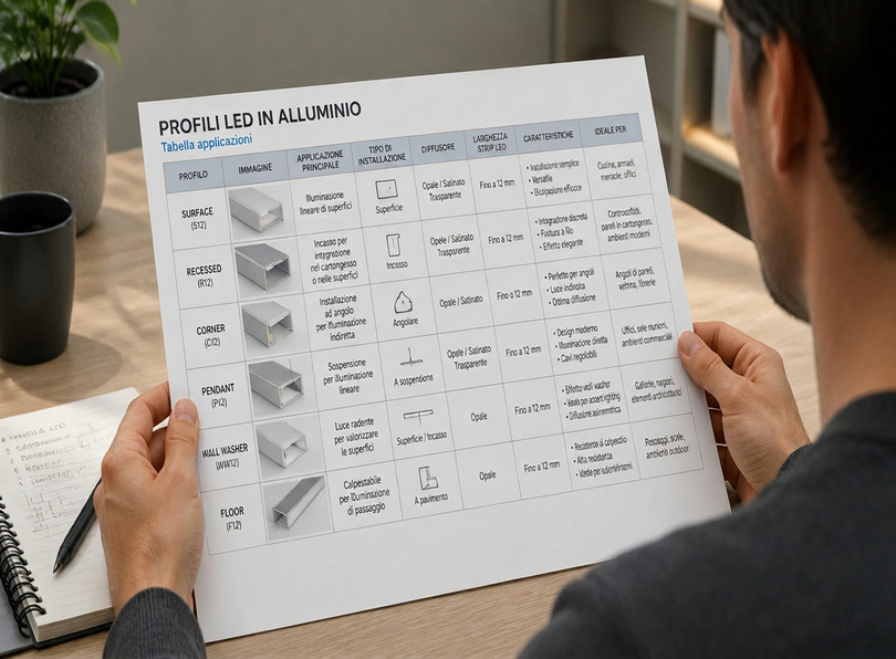
Complete reference table: all profile types, dimensions and applications
| Profile type | Section geometry | Max strip width | Installation depth | Standard diffuser | Thermal dissipation | Primary applications |
|---|---|---|---|---|---|---|
| Flat / Low-Profile | Flat rectangular | 10–12 mm | None (surface flush) | Opaque or transparent | Good | Under-cabinet, furniture, suspended ceiling |
| Standard Recessed | Recessed rectangular | 10–12 mm | 8–12 mm | Opaque or transparent | Very good | Drywall coves, custom cabinetry, bookshelves |
| Wide Recessed | Wide rectangular | 14–20 mm | 10–14 mm | Opaque or transparent | Excellent | COB LED strips, high-power, professional environments |
| 45° Angular | Triangular corner | 8–10 mm | None | Opaque or transparent | Good | Vertical corners, wall/ceiling junctions |
| 60° Angular | Triangular variant | 8–10 mm | None | Opaque or transparent | Good | Non-orthogonal angles, bespoke architectural design |
| U-Shape / Surface Mount | Open U-section | 8–12 mm | None | Opaque or transparent | Good | Wall surfaces, furniture, back panels |
| Stair / Step | Step-integrated form | 8–10 mm | Recessed into riser/tread | Opaque or transparent | Medium | Staircase tread and riser accent lighting |
| Floor / Walkable | Robust walkable body | 8–10 mm | Flush floor recess | Tempered glass | Good | Walkable floors, staircases, signage paths |
| Handrail | Railing-specific form | 8–10 mm | None | Opaque | Medium | Illuminated handrails and balustrade railings |
| Cove / Round Head | Semi-circular | 8–10 mm | None | Opaque | Good | Cove lighting effects, indirect wall grazing |
| Neon Flex | Rounded full-body | LED neon-specific | None | Integral profile material | Medium | Neon effects, signage, decorative outlines |
| TV Backlight | Ultra-thin flat | 8 mm | None | Backlight-specific | Medium | Television, monitor and display backlighting |
Flat and low-profile aluminium LED profiles
Profile heights in this category typically range from 4 mm to 10 mm, with channel widths of 8–20 mm depending on sub-type. The flat geometry allows the profile to be fitted beneath kitchen cabinet carcases, along the underside of shelving, within suspended ceiling voids, and along display furniture back panels without consuming meaningful space or creating visual obstruction.
Flat profile dimensional specifications
| Sub-Type | Profile Height (mm) | Profile Width (mm) | Channel Width (mm) | Standard Length (m) | Typical Weight (g/m) |
|---|---|---|---|---|---|
| Ultra-thin / mini flat | 4–5 | 12–14 | 8–10 | 1 / 2 | 45–65 |
| Standard flat | 6–7 | 14–16 | 10–12 | 1 / 2 | 75–100 |
| Wide flat | 7–10 | 16–24 | 12–20 | 1 / 2 | 110–165 |
Under-cabinet kitchen lighting: correct specification
The under-cabinet kitchen installation is the single most common residential application for flat LED profiles. A poorly specified under-cabinet installation (wrong profile type, wrong diffuser, wrong colour temperature) is one of the most frequent complaints in residential LED lighting, and entirely preventable through correct specification. Optimal specification: flat or mini-flat profile (height ≤ 7 mm); opaque diffuser where visible from adjacent living space, 2835 high-density or 10 mm COB strip at 2700-3000 K, continuous runs joined by connector or solder for a seamless light line. The CCT must match the ceiling lighting to within 200 K to avoid discordant colour contrast.
Mounting methods: snap-fit adhesive clips (light duty, smooth surfaces, no drilling), screw-through fixing through pre-drilled profile base holes (most secure — recommended for cable-loaded or vibration-exposed positions), continuous double-sided tape along the full profile base (best load distribution on smooth non-porous surfaces).
Standard recessed aluminium LED profiles
When correctly specified and installed, the profile effectively disappears — leaving only the light line visible. This is the defining characteristic that separates a professional architectural LED installation from an amateur one: the profile should never be the visual feature, the light line is the feature.
Standard recessed profile dimensions
| Sub-type | Channel width (mm) | Channel depth (mm) | Profile width (mm) | Protrusion (mm) | Max strip width (mm) |
|---|---|---|---|---|---|
| Mini recessed | 8–10 | 8–10 | 12–14 | 0–2 | 8 |
| Standard recessed | 10–12 | 10–12 | 14–18 | 0–3 | 10–12 |
| Deep recessed | 12–14 | 14–16 | 16–20 | 0–4 | 12 |
Architectural cove lighting: the premium application
Cove lighting, indirect illumination of a ceiling surface by an LED strip concealed in a recess in the opposing surface, is the most prestigious and technically demanding application for recessed LED profiles. A correctly executed cove installation produces the impression that the ceiling glows from within, a quality of ambient light that no surface luminaire can replicate. Key specification parameters: wide recessed profile, opaque diffuser (essential), COB strip at 2700 K, CRI ≥ 95; minimum offset from profile to illuminated surface of 150 mm (200–300 mm for optimal uniformity), strip power calculated to produce the required surface luminance using manufacturer photometric data.
Wide recessed profiles for COB and high-power LED strips
| COB strip type | PCB width (mm) | Power (W/m) | Min channel width (mm) | Thermal rating required | Recommended profile |
|---|---|---|---|---|---|
| Standard COB 8 mm | 8 | 8–10 | 8 | Good | Standard recessed or U-shape |
| Standard COB 10 mm | 10 | 10–14 | 10 | Very good | Standard or wide recessed |
| High-power COB 10 mm | 10 | 14–20 | 10 | Excellent | Wide recessed |
| Wide COB 14 mm | 14 | 14–20 | 14 | Excellent | Wide recessed |
| Ultra-high-power COB 15+ mm | 15+ | 20–30 | 15 | Excellent | Wide recessed with enhanced body |
Installing a high-power strip in a standard or mini recessed profile that cannot provide adequate thermal management will result in accelerated lumen depreciation and premature failure, typically visible as colour shift and output reduction within 18–24 months rather than the 8–10 years a correctly thermally managed installation delivers.
Angular LED profiles: 45° and 60° corner solutions
| Profile type | For corner angle | Emission direction | Best application | Notes |
|---|---|---|---|---|
| 45° angular | Standard 90° | 45° bisecting corner | Wall/ceiling junctions, room perimeters | Most common type |
| 60° angular | Non-standard <90° | 60° from one surface | Bay windows, angled architecture | For non-orthogonal corners |
| Internal corner angular | 90° internal | Into the corner | Recessed alcoves, internal corners | Creates shadow line at corner |
The most critical installation detail is the corner treatment at the ends of runs. A powered mitre saw with a non-ferrous blade is essential for acceptable mitre quality in aluminium, a mitre cut 1° out of true across a 20 mm wide profile creates a visible 0.35 mm gap, immediately apparent in a premium installation at normal viewing distances.
U-shape surface mount LED profiles
| Sub-type | Internal width (mm) | Internal depth (mm) | External width (mm) | External height (mm) | Strip widths accepted |
|---|---|---|---|---|---|
| Narrow U (mini) | 8 | 6 | 10 | 8 | 5–8 mm |
| Standard U | 10–12 | 7–8 | 14–16 | 10–12 | 8–12 mm |
| Wide U | 14–20 | 8–10 | 18–24 | 12–14 | 12–20 mm |
The U-shape profile excels in furniture and display lighting (applied to vertical shelf panels and display unit sides), back panel illumination (creating a wash of light across alcoves and display cases), and all retrofit and temporary installation applications where the substrate cannot be modified. Its broad application range and installation simplicity make it one of the highest-volume profile types in the LightingLine range.
Stair and step LED profiles
| Profile type | Tread material | Recess method | Profile width (mm) | Profile depth (mm) | Notes |
|---|---|---|---|---|---|
| Tread-face recessed | Timber, MDF, stone | Routed recess in tread nose | 16–22 | 8–12 | Most common, light directed downward |
| Riser surface mount | All materials | Surface applied to riser face | 16–22 | 8–10 | Simpler installation, profile visible on riser |
| Tread-edge recessed (flush) | Timber, stone | Full recess flush with tread | 18–24 | 10–14 | Premium, fully invisible from above |
| Aluminium stair nosing | All materials | Surface applied — replaces nosing | 40–60 | 4–6 | Combined nosing protector and LED profile |
For commercial staircase applications, specify a tempered glass or heavy-gauge polycarbonate diffuser with a rated impact strength. Never specify a standard polymer diffuser for any stair application in a public or commercial environment, diffuser failure under repeated foot impact is a safety and liability issue, and mid-installation replacement costs substantially more than the correct specification from the outset.
Walkable floor LED profiles
The floor LED profile differs from all other profile types in one critical respect: the cover serves a structural load-bearing function. Cover material, thickness, edge support geometry, and the profile body’s resistance to deflection under load are all primary engineering parameters. The profile must be recessed flush with the finished floor surface to a dimensional precision of ±0.5 mm any protrusion creates a trip hazard under building regulations across all EU member states and the UK (Building Regulation Part K).
Load classification table
| Load class | Max load (kg/m) | Cover material | Typical application | Notes |
|---|---|---|---|---|
| Residential light | 100–150 | Polycarbonate 4 mm | Private residential floors, low traffic | Not for public / commercial use |
| Commercial medium | 200–300 | Tempered glass 6 mm | Office, retail, hospitality | Suitable for regular public foot traffic |
| Heavy commercial | 400–500 | Tempered glass 8 mm | High-traffic retail, airports, stations | Requires robust substrate and fixings |
| Industrial | 1,000+ | Hardened glass / steel | Vehicle-accessible areas, industrial floors | Custom specification required |
Handrail and railing LED profiles
The illuminated handrail is a feature found predominantly in high-end hospitality, premium residential projects and public buildings where architectural lighting quality is a design priority. The LED strip, concealed within the handrail profile and directed downward, creates a glowing light line that provides wayfinding illumination for the staircase below and a distinctive visual signature for the space. When correctly specified, an illuminated handrail transforms a functional safety element into an architectural feature of the first order. Key compatibility parameters: profile width must match the underside surface of the handrail; profile height must allow full clearance above post caps or glass panels; and cable routing must be planned through the handrail to the nearest power feed point. For handrail runs exceeding 5 metres, mid-run voltage injection may be required to maintain uniform brightness across the full length.
Cove and round-head LED profiles
The round-head profile is particularly effective in smaller spaces (bedrooms, corridors, alcoves) where a full architectural cove would consume too much structural depth but where indirect ceiling illumination is strongly desired. The semi-circular body provides mechanical shielding that prevents the LED strip from being visible from below, even without an additional diffuser in some COB strip applications.
| Ceiling height (m) | Profile height from ceiling (mm) | Distance from wall (mm) | Expected wash width (mm) |
|---|---|---|---|
| 2.4 m | 180–220 | 0 | 300–500 |
| 2.7 m | 200–280 | 0–20 | 400–650 |
| 3.0 m+ | 250–350 | 20–40 | 600–900 |
Neon flex LED profiles
LED neon flex is not simply an LED strip inside a silicone profile, the silicone body is an integral optical component whose geometry determines the emission angle, light colour uniformity, and physical appearance of the product. Application contexts where neon flex profiles excel: signage and custom lettering (minimum bend radii 30–150 mm depending on profile width, verify against the minimum radius required by letter form geometry), architectural accent lighting in hotels, nightclubs and premium bars, creating continuous colour accent lines along bar fronts, step risers and wall recesses and decorative and art installations where the sculptural flexibility of the silicone body is required and the light source itself is the visual feature.
TV and monitor backlight LED profiles
Bias lighting reduces the contrast between the bright screen surface and the dark surrounding wall, reducing adaptation stress on the eye. The recommended colour temperature for bias lighting is 6500 K, matching the D65 white point used as the display calibration reference standard.
| Screen size | Strip length (m) | Recommended power (W) | CCT | Profile height |
|---|---|---|---|---|
| 32–43” | 1.5–2.0 | 6–10 | 6500 K | 4–5 mm |
| 43–55” | 2.0–3.0 | 10–15 | 6500 K | 4–6 mm |
| 55–75” | 3.0–4.5 | 14–22 | 6500 K | 5–6 mm |
| 75”+ | 4.5–6.0 | 20–30 | 6500 K | 5–7 mm |
Diffuser selection: opaque vs. transparent — A technical decision
An opaque diffuser contains light-scattering particles suspended in a polymer matrix, redirecting photons to produce a uniform luminous surface. A transparent diffuser allows most photons to pass through with minimal deviation. The practical consequence: the opaque diffuser conceals the LED chip array completely, while the transparent diffuser allows individual LED positions to be seen as brighter spots at close viewing distances.
Comprehensive diffuser comparison
| Characteristic | Opaque diffuser | Transparent / Clear diffuser | Frosted semi-transparent |
|---|---|---|---|
| LED chip visibility | Completely concealed | Visible at all distances | Partially visible at <0.5 m |
| Light uniformity | Excellent — uniform surface | Poor at close range; good at distance | Good at >0.3 m |
| Light transmission | 75–85% | 90–95% | 85–90% |
| Emission angle | Approx. 120° | 120–160° | 120–140° |
| Cove lighting | Essential | Not recommended | Acceptable with COB |
| Mirror surround | Essential | Not acceptable | Marginal |
| Low-density SMD (≤60 LED/m) | Necessary | Not acceptable | Not recommended |
| High-density SMD (120+ LED/m) | Recommended | Acceptable | Good |
| COB strip pairing | Ideal | Unnecessary but acceptable | Good |
Photometric impact: a common specification error is to calculate required LED output using an open-strip efficiency figure and then add an opaque diffuser, resulting in an installation 15–25% below the specified illuminance level. Correct approach: if 800 lm/m is required at the diffuser face, and the opaque diffuser has 80% transmission efficiency, the LED strip must produce 1,000 lm/m at the strip surface (800 ÷ 0.80).
Diffuser materials:
- Polycarbonate (PC): excellent impact resistance, correct for any application where diffuser contact with objects is possible.
- Acrylic (PMMA): superior optical clarity and UV resistance; brittle, not for impact-exposed positions.
- Tempered glass: specified exclusively for walkable floor profiles; rated for load-bearing use.
Recess depth planning: drywall and substrate integration
| Profile type | Housing depth (mm) | Housing width (mm) | Width tolerance | Protrusion after recess (mm) | Notes |
|---|---|---|---|---|---|
| Mini recessed | 8–10 | 12–14 | +0.5 / −0 | 0–2 | For strips max 8 mm PCB |
| Standard recessed | 10–12 | 14–18 | +0.5 / −0 | 0–3 | For strips max 10 mm PCB |
| Wide recessed | 12–16 | 18–24 | +1.0 / −0 | 0–4 | For COB or high-power strips |
| Deep wide recessed | 16–20 | 20–28 | +1.0 / −0 | 0–5 | Ultra-high-power or dual strip |
| U-shape surface mount | 0 (no recess) | — | — | 12–18 | Direct surface application |
| 45° angular | 0 | — | — | 18–25 per side | Corner surface mount; no recess |
| Light cove (architectural) | Profile-dependent | 30–60 (cove) | +2.0 / −0 | Variable | Always resolve with design drawings |
| Floor profile | Profile height + substrate | Profile width + 1.0 mm | +0.5 / −0 | 0 (flush) | Must be ±0.5 mm of floor level |
Correct drywall construction sequence:
Departing from this sequence (most commonly by adding recessed profiles after the wall is finished) substantially increases total installation cost and damages the finished surface
- Frame partition/ceiling
- First-fix electrical rough-in
- Cut profile housings before boarding
- Board drywall
- Tape and fill
- Sand
- Prime
- Install profiles with screws into framing
- Install LED strips and connect cables
- Install diffusers
- Final paint.
LED strip PCB width vs. profile channel width: complete compatibility table
| Strip PCB width | Min profile channel Width | Ideal channel width | Compatible strip types | Notes |
|---|---|---|---|---|
| 5 mm | 5 mm | 5–6 mm | 2216 low-density, narrow format | Limited profile choice, verify with adhesive tape in place |
| 8 mm | 8 mm | 8–9 mm | 8 mm COB, 0807, 2216 high-density | Common COB width, good profile selection |
| 10 mm | 10 mm | 10–11 mm | 2835, 2835 HD, 10 mm COB | Most common width, broadest profile choice |
| 12 mm | 12 mm | 12–13 mm | 5050 RGB, RGBW, 12 mm COB | RGB and wide COB format |
| 14 mm | 14 mm | 14–15 mm | High-power strips, RGBCCT multi-channel | Wide recessed profile required |
| 15 mm | 15 mm | 15–16 mm | High-power COB, special formats | Wide recessed only |
| 20 mm | 20 mm | 20–22 mm | Dual-PCB, ultra-high-density strips | Wide recessed with enhanced body |
The adhesive backing thickness problem: LED strips supplied with 3M-type double-sided foam adhesive tape have an effective width increase of approximately 0.3–0.5 mm per side when inserted into a tight-tolerance channel, because the foam compresses against the channel walls. For any channel width equal to the nominal PCB width, the adhesive tape may prevent insertion. Specify a channel at least 0.5 mm wider than the nominal PCB width to ensure clean insertion with adhesive tape in place. This is the most common cause of “profile won’t accept the strip” issues on site and is entirely preventable at specification stage.
Thermal performance: how aluminium profiles extend LED strip lifespan
| Junction temperature (°C) | Relative lifespan (L70) | Approx. hours to L70 | Typical installation condition |
|---|---|---|---|
| 25°C | 100% (baseline) | 50,000+ | Premium profile, thermally conductive tape, full PCB contact |
| 35°C | ~70% | 35,000 | Standard profile, good contact, normal ambient |
| 45°C | ~50% | 25,000 | Budget profile or elevated ambient temperature |
| 55°C | ~25% | 12,500 | No profile; strip surface-mounted to poor conductor |
| 65°C+ | <15% | <7,500 | No thermal management; confined or enclosed space |
The three alloys most commonly used in LED profile extrusion: 6063-T5 (thermal conductivity ~200 W/m·K, excellent surface finish, preferred for premium profiles), 6061-T6 (~167 W/m·K, higher structural strength, used for floor and heavy-duty profiles), 1000-series commercially pure aluminium (220–240 W/m·K; highest conductivity, used in specialist thermal profiles). All aluminium alloys provide thermal conductivity two to three orders of magnitude superior to any polymer alternative. There is no substitute for aluminium where thermal management is a performance requirement.
Application-by-application technical specification guide
Architectural cove lighting
| Parameter | Specification | Rationale |
|---|---|---|
| Profile type | Wide recessed, integrated into drywall | Maximum uniformity, COB strip accommodation |
| Diffuser | Opaque — essential | Prevents LED chip pattern on ceiling surface |
| LED strip | COB 10 mm, 2700 K, CRI ≥ 95 | Inherent uniformity, warm architectural tone |
| Strip power | 10–16 W/m (ceiling height dependent) | Higher power required for taller ceilings |
| Offset to ceiling | Min. 150 mm, optimal 200–300 mm | Prevents visible bright-spot non-uniformity |
| Common errors | Transparent diffuser, insufficient offset, low-density strip | Each produces visible non-uniformity |
Bathroom mirror surround lighting
Mirror surround lighting places unique demands on profile specification. The profile must appear integral to the mirror frame; the LED strip must deliver CRI ≥ 95 (ideally R9 > 80) for accurate skin tone rendering; and CCT should be 3500–4000 K. The opaque diffuser is non-negotiable, the mirror surface creates a reflected view of the profile body at any vertical angle, meaning that LED chips visible through a transparent diffuser appear directly in the reflection, immediately apparent to any observer.
Retail display and commercial accent lighting
Research by the Retail Design Institute consistently demonstrates that higher illuminance levels at point of display increase perceived merchandise value. Priority specification parameters for retail: CRI ≥ 95 with R9 > 50, CCT matched to brand identity (2700–3000 K for luxury/warm, 4000 K for food retail), transparent diffuser where maximum luminous output per metre is required, profiles with no visible fixing hardware when viewed from the sales floor.
Hospitality: hotels, restaurants and bars
Hospitality lighting demands the highest combined performance across all specification parameters: visual quality (opaque diffusers throughout), colour rendering (CRI ≥ 95), CCT consistency across all profiles in a space (within ±100 K), mechanical robustness, and operational reliability. The LightingLine recessed and wide recessed range, specified with opaque diffusers and COB strips, meets all of these requirements simultaneously and delivers the 50,000+ hour service life expected of a commercial installation.
Installation best practices and common errors
| # | Error | Consequence | Prevention |
|---|---|---|---|
| 1 | Profile too narrow for strip PCB | Strip cannot be inserted, PCB bent on forcing | Verify channel width ≥ PCB width + 0.5 mm before ordering |
| 2 | Housing cut too tight | Profile cannot be inserted without substrate damage | Add 0.5 mm per side to housing width vs. profile outer width |
| 3 | Wrong diffuser type | LED chips visible at close range, poor visual quality | Specify opaque for any close-proximity or cove application |
| 4 | Inadequate thermal contact | Accelerated LED degradation, colour shift, early failure | Use thermally conductive tape, ensure strip is fully flat in channel |
| 5 | Profile housing in wrong position | Light misses target surface, cove uniformity insufficient | Resolve position with dimensioned drawings before substrate work |
| 6 | No end caps fitted | Exposed cable; dust ingress, unprofessional finish | Always fit end caps, order correct type with profile |
| 7 | LED polarity reversed | Strip does not illuminate, potential driver damage | Mark polarity at all connection points, check before power-on |
| 8 | Runs too long for voltage drop | Visible dimming at far end, colour shift in CCT strips | Calculate voltage drop for all runs >5 m, feed from both ends if required |
| 9 | High-power strip in inadequate profile | Overheating, accelerated failure, potential fire risk | Verify strip wattage vs. profile thermal rating before specifying |
| 10 | Mitre joints not cut accurately | Visible gaps at corner joints, poor visual quality | Use powered mitre saw with non-ferrous blade, test cut on waste first |
Every LED profile installation should include a cable routing plan produced at the design stage. Minimum bend radius for LED strip cables: never bend at less than 10× the cable diameter. Use crimp or solder connections for all permanent installations, push-in connectors are for testing only. For bathroom or exterior profiles requiring cable entries, use adhesive-lined heat-shrink over all solder joints and seal cable entries with silicone sealant to maintain the IP rating.
Exterior and IP-rated profile installations
| Location type | Min. strip IP | Min. driver IP | Profile requirement | Diffuser requirement |
|---|---|---|---|---|
| Dry interior | IP20 | IP20 | Standard anodised | Standard PC or acrylic |
| Bathroom zone 2 | IP44 | IP44 | Standard; sealed end caps | Sealed moisture-resistant |
| Bathroom zone 1 (shower) | IP65 | IP65 remote | Sealed; waterproof end caps | IP65-rated diffuser |
| Exterior covered (canopy) | IP65 | IP65 | Anodised; waterproof end caps; UV diffuser | UV-stabilised PMMA or PC |
| Exterior exposed (façade) | IP67–IP68 | IP67 | Marine-grade anodising; fully sealed | UV-stabilised; hardened |
| Submerged (pool / fountain) | IP68 (rated depth) | IP67 remote | Fully sealed; potted | Tempered glass; sealed gasket |
Thermal expansion in exterior installations: The coefficient of thermal expansion of aluminium (23.1 × 10−⁶ /°C) means a 2-metre profile run will expand by approximately 2.3 mm across a 50°C temperature range, typical for European outdoor conditions. For runs exceeding 1 metre, expansion joints must be provided at maximum 1-metre intervals. Silicone-encapsulated LED strips are substantially more tolerant of differential thermal movement than bare PCB strips.
COB LED strips and profile compatibility: a special case
COB strips produce seamless, continuous light emission with no visible chip positions at any viewing distance. This makes the transparent vs. opaque diffuser decision less critical than for SMD, a transparent diffuser on a COB strip will not reveal individual chip positions. However, an opaque diffuser still produces a more refined luminous surface appearance and is the preferred specification for all premium architectural applications.
| COB strip format | PCB width | Power (W/m) | Compatible profile types | Recommended diffuser |
|---|---|---|---|---|
| Narrow COB | 5–8 mm | 5–10 | Mini recessed, narrow U-shape | Opaque or transparent |
| Standard COB | 10 mm | 8–14 | Standard recessed, U-shape, flat | Opaque preferred |
| High-power COB | 10–12 mm | 14–20 | Wide recessed | Opaque, strongly recommended |
| Wide-format COB | 14–16 mm | 16–25 | Wide recessed, wide U-shape | Opaque |
| Dual-row COB | 20+ mm | 25–40 | Wide recessed with enhanced body | Opaque, essential |
Market research: how professionals specify LED profiles in Europe
| Survey finding (European LED lighting market 2024) | Result |
|---|---|
| Residential LED strip installations using aluminium profiles (EU, 2024) | 58% |
| Commercial LED strip installations using aluminium profiles (EU, 2024) | 87% |
| Most common specification error cited by professional installers | Wrong diffuser type (42%) |
| Second most common error | Profile channel too narrow for strip PCB (31%) |
| Most rapidly growing profile type 2022–2024 by volume | Wide recessed for COB strips (+340%) |
| Specifiers requiring CRI ≥ 95 on residential projects | 67% |
| Primary purchase decision criterion for profiles | Dimensional accuracy and finish quality (73%) |
| Architects specifying profile as a named product | 73% (up from 41% in 2019) |
| COB strip share of European LED strip market (2024) | ~45% and growing |
| Projected COB strip share by 2026 | >55% |
Emerging trends through 2027: the dominance of COB strips will drive further growth in wide-channel recessed profiles and make the opaque diffuser the default specification for most architectural applications. RGBCCT and tunable white strips (requiring wider PCBs) are growing rapidly in premium residential and hospitality sectors. European procurement specifications are increasingly requiring certified recycled aluminium content in extrusion products. Ultra-thin profiles below 5 mm are a rapidly growing category driven by furniture, mirror and TV mounting applications.
FAQ: Aluminium LED profiles — Technical questions answered
| Frequently Asked Questions — click any question to expand the full answer |
|---|
An aluminium LED profile simultaneously delivers three distinct engineering functions. First, mechanical protection: the aluminium body shields the LED strip PCB from impact, abrasion, flexural stress and contamination, protecting solder joints, chip connections and PCB substrate from damage that would cause premature electrical failure. Second, thermal dissipation: the aluminium body conducts heat away from the LED junction through the PCB base, reducing junction temperature and exponentially extending service life — every 10°C reduction in junction temperature approximately doubles projected LED lifespan. Third, optical function: the diffuser conceals the LED chip array from direct view, producing a uniform luminous surface, and shapes the angular distribution of emitted light to suit the application. A quality aluminium profile optimises all three functions simultaneously. |
Specify an opaque diffuser whenever: the profile will be visible at a viewing distance of less than 2–3 metres; the installation uses an SMD LED strip with fewer than 120 LEDs/m; the application is a light cove, mirror surround, display unit, or any other premium interior context; or the specification calls for a continuous, uniform light line with no visible chip pattern. Specify a transparent diffuser when: maximum luminous output per metre is the priority; the profile will not be in direct sightline of occupants at close range; the application is utility (workshop, storage, garage); or the LED strip is a COB type. Never specify a transparent diffuser on a low-density SMD strip for any application where the profile is visible from occupied areas at close range. |
For surface-mount profiles (flat, U-shape, angular), three methods are available: snap-fit adhesive mounting clips supplied with the profile (light-duty, smooth clean substrates, no drilling); direct screw fixing through pre-drilled holes in the profile base (most secure — recommended wherever cable pull or vibration is possible); and continuous double-sided high-bond tape along the full profile base (best load distribution on smooth non-porous surfaces). For recessed profiles, the profile is inserted into the pre-cut substrate housing and fixed with screws into the housing walls. Ensure the substrate has sufficient structural depth and rigidity — never fix a recessed profile into unsupported plasterboard alone. |
Yes — significantly and measurably. A 10 W/m LED strip installed without thermal management may operate at a junction temperature 20–30°C above the same strip in a quality aluminium profile with full PCB contact. At 25°C above baseline junction temperature, the L70 lifespan is approximately halved. In practical terms: a strip rated for 50,000 hours at 25°C may deliver only 12,500–25,000 hours at 45–55°C junction temperature. A premium aluminium profile with full PCB contact and thermally conductive adhesive tape can realistically maintain junction temperatures within 10°C of the 25°C baseline on strips up to 10 W/m. The correct profile specification can mean the difference between one strip replacement in ten years and three. |
Yes. Aluminium profiles can be cut to any length using a fine-tooth hacksaw (minimum 32 TPI) or, preferably, a powered mitre saw with a non-ferrous metal cutting blade. A powered saw produces a significantly cleaner, more accurate cut, particularly important for 45° mitre joints at room corners. After cutting, deburr the cut end with a fine file or deburring tool before inserting the LED strip, to prevent aluminium swarf from penetrating the PCB or strip insulation. For precision mitre joints, a powered mitre saw with a calibrated 0.5° stop is strongly recommended, a mitre cut 1° out of true across a 20 mm profile face creates a visible 0.35 mm gap immediately apparent in a finished premium installation. |
For a standard recessed profile accepting 10–12 mm PCB strips, the housing depth is typically 10–12 mm and the housing width is typically 14–18 mm but always download the dimensioned technical drawing from the LightingLine product page for the specific profile you are specifying. Add +0.5 mm to the housing width to allow clean insertion. In drywall installations, the housing must be backed by a timber or steel framing element (never cut a recessed housing into unsupported plasterboard. The housing must be prepared before taping, filling and painting) corrections after surface finish is applied are expensive and disruptive. |
For the most common 10 mm COB strips at standard power (8–14 W/m), a standard recessed profile with a 10 mm channel delivers adequate thermal management. For high-power COB (14–20 W/m) or wide-format COB (14–16 mm PCB), a wide recessed profile is the correct specification. For surface-mount COB applications, a U-shape or flat profile matching the COB PCB width is appropriate. In all cases, an opaque diffuser is recommended even though COB strips are inherently uniform, the opaque diffuser converts the direct view of the COB phosphor layer into a refined glowing surface that produces the most professional finished appearance. |
A purpose-built walkable floor LED profile with a certified load class appropriate to the anticipated traffic intensity. The cover must be tempered glass (not polycarbonate or acrylic) for any public or commercial floor application. The profile body must be recessed flush with the finished floor surface to a precision of ±0.5 mm. For residential use, a 150–200 kg/m rating is typically sufficient. For commercial public areas, specify a minimum of 300 kg/m with at least 6 mm tempered glass. Never specify a standard LED profile for floor installation — standard profiles are not load-rated and will fail under foot traffic. |
For exposed exterior installations, the LED strip must carry a minimum IP65 rating, and IP67 or IP68 for applications subject to immersion. The profile body must be anodised aluminium with full corrosion resistance, sealed with waterproof end caps. The diffuser must be UV-stabilised, standard polycarbonate without UV stabilisation will yellow and become brittle within 12–24 months of direct outdoor exposure. The LED driver must also be rated for outdoor use at minimum IP65. Cutting an IP-rated strip and re-terminating it in the field invalidates the IP rating unless the re-termination is performed with adhesive-lined heat-shrink waterproofing over all solder joints. |
No. A standard white or opal diffuser in polycarbonate or acrylic does not materially alter the CCT of the LED strip. It scatters and uniformises light by redirecting photons but does not filter specific wavelengths and therefore does not shift the spectral distribution in a way that changes perceived colour temperature. Yellow-tinted or amber-tinted diffusers would shift CCT toward warmer values, but these are specialist products not used in standard architectural applications. A frosted or opaque diffuser can make the emitted light appear marginally softer in perception, this is a perceptual effect, not a photometric spectral shift. |
Explore the LightingLine aluminium LED profile range
The LightingLine collection offers a comprehensive selection of extruded aluminium LED profiles designed to accommodate a wide variety of lighting applications, from surface-mounted and recessed installations to pendant and corner configurations. For each profile type referenced in this guide, you can find the corresponding product page on the LightingLine range provides complete technical documentation.
This includes precise CAD-quality technical drawings, full dimensional specifications (including internal/external widths and mounting depths), compatibility data for diffuser options (such as clear, frosted, semi-frosted, or opal finishes) and a complete list of compatible accessories, including mounting clips, end caps, connecting brackets, and joining kits. All of this information is systematically organised on every individual product page to support informed selection, seamless integration, and efficient installation.