The surface mount LED profile is the most widely used aluminium LED housing in Europe and also the most frequently misspecified. The decision between a slim flat profile and a wide deep-channel surface mount, between a frosted and an opal diffuser, between 10 mm and 17 mm channel width, between clip-mounted and adhesive-fixed: each of these choices determines whether the finished installation looks professionally designed or makes it immediately visible that the cheapest option was chosen. This guide covers every dimension, every diffuser type, every fixing method, every thermal parameter, and every installation technique you will ever need.
In this article…
- What is a surface mount LED profile and why does it matter?
- Surface mount vs recessed vs corner: how to choose the right profile type
- Types of surface mount LED profile: from slim flat to wide high-output
- Surface mount LED profile dimensions: width, height and compatibility
- Diffusers for surface mount LED profiles: frosted, opal, transparent
- Thermal management: how surface mount profiles extend LED life
- Fixing and mounting surface mount LED profiles
- Cutting surface mount LED profiles: tools, technique and precision
- Installing LED strip in surface mount profiles: the professional method
- Surface mount LED profile applications by room and sector
- Selecting the right LED strip for surface mount profiles
- Power supply and driver selection for surface mount LED systems
- LightingLine.eu Surface Mount LED Profile Range
- Specification guide for architects and contractors
- Maintenance, cleaning and long-term performance
- FAQ — Professional answers about surface mount LED profiles
- The surface mount LED profile decision is a quality decision
What is a surface mount LED profile and why does it matter?
A surface mount LED profile (also called a surface LED channel, surface LED extrusion, or surface-mounted LED aluminium housing) is the most fundamental component of any professional linear LED lighting installation. It is an extruded aluminium channel designed to be fixed directly to a ceiling, wall, worktop underside, shelf, floor edge, or any other surface, without requiring any structural integration, routing, or preparation of the substrate. The LED strip sits inside the channel; the aluminium acts as a heat sink; and a polycarbonate or PMMA diffuser clips into the channel mouth to control glare, achieve visual uniformity, and protect the strip from dust and physical contact.
The surface mount LED profile is favoured for two reasons above all others: installation simplicity and universal compatibility. Unlike recessed profiles, which require precise routing of plasterboard or a prepared housing in a suspended ceiling grid, a surface mount profile can be fixed to virtually any substrate (plasterboard, plywood, brick, concrete, MDF, steel) with standard fixings. This makes it the go-to choice for retrofit projects, for applications where ceiling void depth is insufficient for recessing, and for all furniture-integrated lighting where routing is impractical. Approximately 65% of all aluminium LED profile installations across Europe use surface mount profiles, making them the dominant format in both residential and commercial markets.
Yet despite this ubiquity, surface mount LED profiles are chronically under-specified in much of the market. The difference between a cheap extruded profile from an unspecified source and a precision-manufactured Italian-designed surface mount profile is functional. Channel width precision determines whether the LED strip fits correctly and makes full thermal contact with the base. Alloy grade determines thermal conductivity and therefore LED longevity and diffuser optical quality determines whether the finished light output is smooth and professional or visibly dotted and amateur. The fixing system design determines whether the profile stays perfectly straight and flush for twenty years, or begins to show stress points and deflection within two. This guide addresses every one of these parameters in the depth that professional specification demands.
Surface mount vs recessed vs corner: how to choose the right profile type
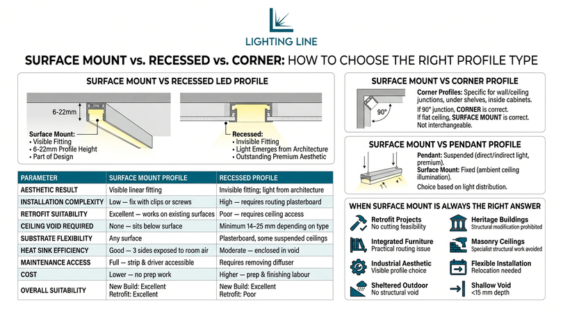
Before specifying a surface mount LED profile for any project, it is essential to confirm that surface mounting is the correct approach for that specific application. The three main profile installation categories (surface mount, recessed, and corner/angular) each have distinct aesthetic outcomes, structural requirements, and specification implications. Choosing the wrong category produces a result that cannot be corrected without replacing the entire installation.
Surface mount vs recessed LED profile
The fundamental aesthetic difference between surface mount and recessed is the relationship between the luminaire and the surface it is mounted on. A surface mount profile projects away from the ceiling or wall by the profile height (typically 6–22 mm depending on type), creating a visible linear fitting that reads as a distinct element of the room composition. A recessed profile disappears into the ceiling plane, with only the diffuser visible flush with the plasterboard creating an effect where light appears to emerge from the architecture itself rather than from a fitting.
| Parameter | Surface mount LED profile | Recessed LED profile |
|---|---|---|
| Aesthetic result | Visible linear fitting; profile is part of the design composition | Invisible fitting; light appears from within the architecture |
| Installation complexity | Low — fix to surface with clips or screws | High — requires routing of plasterboard or prepared grid slot |
| Retrofit suitability | Excellent — works on any existing surface | Poor — requires access to ceiling void and new plasterboard work |
| Ceiling void required | None — profile sits entirely below ceiling surface | Minimum 14–25 mm depending on profile type |
| Substrate flexibility | Any surface (plasterboard, timber, brick, steel, MDF) | Plasterboard, some suspended ceiling systems only |
| Heat sink efficiency | Good — profile exposed to room air on 3 sides | Moderate — profile enclosed in ceiling void; less convective cooling |
| Maintenance access | Full — strip and driver accessible without damage to ceiling | Requires removal of diffuser to access strip |
| Cost | Lower — no preparation work | Higher — preparation and finishing labour |
| New build suitability | Excellent | Excellent |
| Retrofit suitability | Excellent | Poor |
| Premium aesthetic result | Good to very good depending on profile design | Outstanding — the premium specification |
Surface mount vs corner profile
Corner profiles (angular aluminium extrusions, typically at 45° or 90°) are designed specifically for installation at wall/ceiling junctions, inside cabinet corners, or under shelf edges — positions where neither a flat surface mount nor a recessed profile can be physically accommodated. If the installation position is at a 90° junction between two surfaces, a corner profile is the correct specification. If the installation position is on a flat surface (ceiling, wall, shelf underside, floor edge), a surface mount profile is correct. The two types are not interchangeable.
Surface mount vs pendant profile
Pendant profiles are suspended from the ceiling on cables, rods, or conduit at a height above the working plane determined by the lighting design. They deliver the dual-function direct/indirect (up/down) light output that is the premium specification for open-plan offices and co-working spaces. Surface mount profiles are fixed to the ceiling. The choice between them is determined entirely by the desired light distribution: if ceiling-mounted ambient illumination is required, surface mount is correct. If direct task illumination at desk level combined with indirect ceiling uplighting is required, pendant profiles are the specification.
When surface mount is always the right answer
Surface mount LED profiles are the unambiguous correct choice in the following situations:
- Retrofit projects where cutting into an existing ceiling is not feasible or not permitted
- Listed or heritage buildings where structural modification of ceiling or wall surfaces is prohibited
- Furniture-integrated lighting (under-cabinet, inside wardrobes, within bookshelves, under kitchen units) where routing is impractical
- Concrete or masonry ceilings where creating a recess would require specialist structural work
- Exposed industrial aesthetic where the visible profile is a deliberate design choice
- Temporary or flexible installations requiring future relocation or repositioning
- Outdoor and sheltered external applications where a surface is available but no structural void exists
- Any application with ceiling void depth below 15 mm — insufficient for most recessed profiles
Types of surface mount LED profile: from slim flat to wide high-output
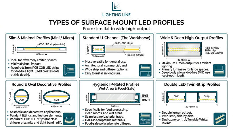
The surface mount LED profile category is not a single product but a family of profiles spanning a very wide range of dimensions, forms, and performance characteristics. Selecting the correct sub-type within the surface mount family is as important as selecting the surface mount category itself. The following sections describe each sub-type in detail, including the applications for which each is the correct choice and the applications for which it is categorically wrong.
Slim flat profiles (mini / micro surface mount)
Slim flat surface mount profiles are the narrowest and shallowest members of the surface mount family, typically 6–12 mm wide and 5–8 mm high. They are specifically designed for applications where the profile must be as visually minimal as possible and where the available space is extremely limited: under the front lip of a kitchen wall unit, inside a recessed shelf reveal, at the front of a display shelf edge, or integrated into joinery details where a larger profile would be incompatible with the surrounding millwork.
The defining characteristic of slim flat surface mount profiles is that they require COB LED strips. Because the profile depth (distance from LED PCB to the diffuser) is typically only 5–8 mm, SMD LED strips produce visible individual LED dots through any diffuser at this depth. Only the continuous phosphor layer of a COB strip achieves dot-free light at these minimal depth dimensions. LightingLine.eu’s slim flat surface mount profiles are specifically matched to the 3 mm PCB width COB strips in the catalogue, ensuring compatibility and dot-free output even with transparent diffusers.
The 3 mm PCB width COB strip at 480 LED/m is specifically designed for slim surface mount profiles. At 6 W/m with a 3 mm PCB, it delivers uniform dot-free illumination in profiles as narrow as 6 mm internal width. This combination (3 mm COB strip + slim surface profile + transparent diffuser) is the standard specification for invisible shelf-edge lighting and ultra-minimal under-cabinet installations.
Standard U-channel surface profiles
Standard U-channel surface mount profiles are the workhorse of the LED profile market: rectangular-section aluminium extrusions with a flat base, two vertical side walls, and two inward-facing lips at the top that retain the diffuser. They are available in channel widths from 10 mm to 20 mm and profile heights from 8 mm to 16 mm, covering the full range of common LED strip PCB widths and providing adequate diffuser depth for both COB and SMD strip technologies.
Standard U-channel surface profiles are the correct specification for the vast majority of architectural, commercial, and residential surface lighting applications: office ambient, under-cabinet task lighting, retail shelving, bathroom vanity, stair risers, and cove lighting. They accept the widest range of diffuser options and LED strip widths, and their rectangular cross-section makes them the easiest profile to fix level and straight over long continuous runs. At the 12 mm internal channel width and 12 mm height configuration, a standard frosted diffuser with a 2835 SMD 24V strip at 14 W/m achieves an output of approximately 1,600 lm/m with a UGR below 22 in typical room geometries: adequate for retail ambient, residential general illumination, and office task supplementary lighting.
Wide and deep high-output surface profiles
Wide and deep surface mount profiles (channel width 20–45 mm, profile height 18–25 mm) are designed for applications requiring the maximum lumen output from a surface-mounted system. They are the specification for commercial ambient lighting where the surface mount profile is the primary luminaire: retail general, office where recessing is not feasible, warehouse or industrial areas with specific surface geometry constraints, and high-output display or signage backlight.
The increased depth of these profiles (18–25 mm from LED PCB to diffuser) allows SMD strips at high density (120 LED/m, 2835) to be used with a frosted diffuser and achieve a fully dot-free result, without requiring the more expensive COB technology. This makes wide deep surface profiles the cost-optimised choice for high-output commercial ambient where the profile is not in close viewing proximity: suspended above head height in a warehouse, fitted below deep kitchen wall units in a large catering kitchen, or positioned high on a retail wall above stock.
Round and oval surface profiles
Round and oval surface mount profiles are cylindrical or elliptical aluminium extrusions designed for applications where the circular cross-section is an aesthetic requirement: pendant decorative fittings (where the profile is surface-mounted to a visible backing plate or ceiling rose), furniture edge lighting where the profile curves around a radius, and architectural feature elements where a round profile reads as a designed object rather than a utilitarian fitting.
Round surface profiles require COB LED strips in all but the largest diameters (above 25 mm diameter), because the curved diffuser surface is typically at very close proximity to the LED strip and produces visible hot-spots with SMD technology. The flexibility of COB strip on its PCB also allows it to flex slightly to follow small-radius curves in oval profiles without the cracking risk associated with SMD strip at tight bend radii.
Hygienic IP-rated surface profiles for wet areas and food environments
Hygienic surface mount LED profiles are a distinct sub-category engineered specifically for environments where washdown, chemical cleaning, and contamination prevention are primary concerns: commercial kitchens, food production facilities, cold stores, pharmaceutical clean rooms, swimming pool machine rooms, and healthcare wet areas. They differ from standard surface profiles in four critical ways: seamless aluminium body geometry with no exposed recesses or joints that could harbour bacteria IP65 minimum (IP69K for high-pressure hot-wash environments) sealing of both the strip channel and the diffuser seal, food-safe polycarbonate diffusers without coatings that could contaminate food or pharmaceutical products and HACCP-compatible marking for traceability.
Installing a standard surface mount profile in a commercial kitchen is a food hygiene violation in most EU jurisdictions under Regulation (EC) No 852/2004 (food hygiene for foodstuffs). The standard profile’s internal corners and diffuser retention channels are impossible to clean completely and create conditions for microbial growth. Always specify hygienic surface profiles in any environment subject to food hygiene or pharmaceutical GMP inspection.
Double LED surface profiles for very high output
Double LED surface mount profiles (also called twin-strip or dual-channel profiles) are wide-body surface extrusions containing two parallel LED strip channels, allowing two independent LED strips to be installed side by side in a single profile body. This configuration doubles the lumen output per linear metre without requiring two separate profiles, and it allows the two strips to be wired to different drivers or control circuits: enabling dual-zone control, tunable white (one strip 2700K, one strip 6500K) from a single profile, or RGBW configurations where the white and colour channels are independently powered.
Surface mount LED profile dimensions: width, height and compatibility
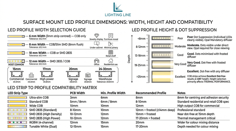
Understanding the dimensional relationships between LED profile width, profile height, LED strip PCB width, and diffuser depth is the foundation of correct surface mount profile specification. These dimensions are interdependent: specifying a profile whose channel is wider than the LED strip PCB causes the strip to sit off-centre, creating uneven heat transfer and potentially allowing the strip to shift position over time. Specifying a profile whose channel is narrower than the strip PCB makes installation physically impossible.
Choosing the right channel width
| Channel width | LED strip PCB width | Technology | Primary applications | Tolerance |
|---|---|---|---|---|
| 6 mm | 3 mm strip (centred) | COB only | Ultra-slim shelf edge, jewellery display, furniture reveal | ±0.2 mm |
| 8 mm | 8 mm strip (flush) | COB or slim SMD | Slim under-cabinet, minimal joinery, mirror edge | ±0.2 mm |
| 10 mm | 8 or 10 mm strip | COB or SMD 2835 | General residential, retail shelf, bathroom vanity | ±0.3 mm |
| 12 mm | 10 or 12 mm strip | SMD 2835 / COB | Office ambient, residential, retail — most common width | ±0.3 mm |
| 15 mm | 12 or 15 mm strip | SMD 2835 high density | Mid-output commercial, retail general, kitchen ceiling | ±0.3 mm |
| 17 mm | 15 mm strip | SMD 2835 high power | High-output commercial ambient, industrial task | ±0.4 mm |
| 20 mm | 15 or 20 mm strip | SMD / RGBW / TW | Commercial high-output, tunable white, RGBW | ±0.4 mm |
| 24–30 mm | 20–24 mm strip or double strip | High-power SMD | Very high output commercial, warehouse, signage backlight | ±0.5 mm |
Profile height and diffuser depth
The profile height (the vertical distance from the base of the channel (where the LED strip sits) to the top of the diffuser when installed) determines two critical performance parameters: dot suppression for SMD strips, and the thermal convective envelope around the LED strip. Greater profile height improves both. For COB strips, height is less critical for optical performance because the continuous phosphor layer eliminates dots regardless of diffuser proximity, but greater height still improves thermal performance by providing more convective airflow around the LED junction.
| Profile height (LED to diffuser) | SMD dot suppression | COB dot suppression | Diffuser required (SMD) |
|---|---|---|---|
| Below 8 mm | Poor — individual LEDs clearly visible | Excellent — dots invisible | Opal (milk-white) mandatory |
| 8–12 mm | Moderate — dots visible under direct view | Excellent | Opal required for close viewing |
| 13–18 mm | Good — dots minimised with frosted diffuser | Excellent | Frosted adequate for most applications |
| 19–25 mm | Very good — dot-free with frosted diffuser | Excellent | Frosted or transparent depending on view angle |
| Above 25 mm | Excellent — dot-free with any diffuser | Excellent | Any diffuser acceptable |
LED strip compatibility by profile width — Complete matrix
| LED strip | PCB width | Min. profile width | Recommended profile | Notes |
|---|---|---|---|---|
| COB 480 LED/m ultra-slim | 3 mm | 6 mm | 8 mm | Use 8mm for centring and adhesion security |
| COB 480 LED/m standard | 5 mm | 6 mm | 8–10 mm | Standard residential and retail COB spec |
| COB 480 LED/m wide | 8 mm | 8 mm | 10 mm | Most common COB profile pairing |
| COB 480 LED/m — 10 mm PCB | 10 mm | 10 mm | 12 mm | High output COB for commercial |
| SMD 2835 — 60 LED/m | 8 mm | 8 mm | 12 mm + opal | Low density — needs depth for dot suppression |
| SMD 2835 — 120 LED/m (standard) | 8–10 mm | 10 mm | 12 mm + frosted (≥14 mm deep) | Professional standard |
| SMD 2835 — 168 LED/m (high density) | 10–12 mm | 12 mm | 15 mm + frosted | Near dot-free at 15 mm depth |
| SMD 2835 — 24 W/m high power | 10–12 mm | 12 mm | 17–20 mm + frosted | Thermal management critical — wide profile |
| RGBW — 4-channel | 12 mm | 15 mm | 20 mm | Wider for colour mixing distance |
| Tunable white — dual channel | 12–15 mm | 15 mm | 17–20 mm | Two LED rows need mixing depth |
Diffusers for surface mount LED profiles: frosted, opal, transparent
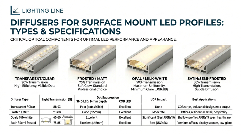
The diffuser is the optical component of the surface mount LED profile that transforms the raw, punctuated, high-brightness output of the LED strip into the smooth, controlled, comfortable luminance that defines professional linear lighting. Selecting the wrong diffuser type for the profile depth and LED strip technology is the single most common optical specification error in LED profile installations and the one that is most immediately visible to anyone who looks at the finished installation.
Frosted diffuser — The standard professional choice
The frosted diffuser is a polycarbonate or PMMA extrusion with a micro-textured or chemically etched surface that scatters transmitted light, creating a softly glowing appearance rather than the appearance of individual bright points. Light transmission is typically 70–80%, meaning approximately 20–30% of the lumen output is sacrificed for the optical improvement. The frosted diffuser is the correct standard specification for all surface mount LED profiles used in office, retail, hospitality, and residential ambient applications where the profile is within normal viewing distance.
The minimum profile depth at which a frosted diffuser achieves dot-free performance with SMD LED strips is approximately 13–15 mm. Below this depth, the frosted surface scatters light but does not fully blend the light cones from individual LED packages, and individual LED positions remain visible as brighter regions of the diffuser. Above 18–20 mm depth, the frosted diffuser achieves excellent dot suppression even with SMD strips at 60 LED/m.
Opal diffuser — Maximum uniformity, minimum glare
The opal diffuser is a milk-white polycarbonate or PMMA extrusion with a high scattering content that reduces light transmission to 45–60% but achieves the maximum possible uniformity of luminance across the diffuser surface. Even at profile depths below 10 mm, the opal diffuser fully suppresses individual LED dots for SMD strips. The opal diffuser is the mandatory specification for shallow surface mount profiles (below 13 mm depth) with SMD strips, and the premium choice for any application where UGR control is critical (open-plan office, healthcare, education).
The trade-off for the opal diffuser’s superior optical uniformity is significant: at 45–60% transmission, the opal absorbs 40–55% of the lumen output that the LED strip produces. For applications targeting specific lux levels, the LED strip wattage must be specified accordingly: a 14 W/m strip with an opal diffuser will deliver approximately the same lux as an 8–9 W/m strip with a frosted diffuser at the same profile depth. Always calculate lux budgets using the diffuser transmission factor applicable to the specific product specified.
Transparent diffuser — Maximum efficiency with COB
The transparent (clear) diffuser achieves light transmission of 88–93% (the highest of any diffuser type) while providing minimal optical diffusion. For COB LED strips, the transparent diffuser is the recommended specification: COB’s continuous phosphor layer eliminates visible LED dots regardless of diffuser proximity, so the high-scattering function of a frosted or opal cover is unnecessary. Using a transparent diffuser with COB strips delivers near-maximum lumen output with the clean, bright-line appearance that defines architectural COB installations.
For SMD LED strips, the transparent diffuser should only be used in profiles of 25 mm depth or greater, and even then only where the profile will not be in direct sight lines at close range. At shallower depths with SMD strips, the transparent diffuser will clearly show individual LED positions: sometimes as a deliberate design choice in industrial or exposed settings, but never acceptable in a professional residential or commercial context.
Diffuser comparison table
| Diffuser type | Light transmission | Dot suppression — COB | Dot suppression — SMD (at 14mm depth) | UGR impact | Best for |
|---|---|---|---|---|---|
| Transparent / Clear | 88–93% | Excellent — no dots visible | Poor — all LED positions visible | None | COB strips, industrial exposed design, maximum output |
| Frosted / Matt | 70–80% | Excellent | Good at ≥15 mm depth; moderate at <13 mm | Moderate reduction | Most architectural applications, office, residential, retail |
| Opal / Milk-white | 45–60% | Excellent | Excellent at any depth ≥6 mm | Significant reduction — best UGR control | Shallow profiles with SMD, office UGR≤19, healthcare, education |
| Satin / Semi-frosted | 80–88% | Excellent | Moderate at <15 mm; good at ≥18 mm | Light reduction | Residential premium, hospitality, display |
Thermal management: how surface mount profiles extend led life
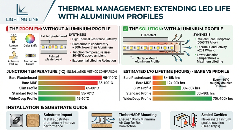
The thermal management function of the aluminium LED profile is not secondary to its optical function: it is arguably more important, because elevated LED junction temperature is the primary cause of lumen depreciation, colour shift, and premature failure in every LED lighting product ever manufactured. The relationship between junction temperature and LED lifetime is exponential: every 10°C increase in junction temperature roughly halves the expected L70 lifetime. An LED strip operating at 85°C junction temperature will reach L70 in approximately 25,000 hours. The same strip operating at 65°C will reach L70 at approximately 100,000 hours. The aluminium profile is the most cost-effective and reliable method of achieving this 20°C reduction.
How heat damages led strips without a profile
An LED strip mounted directly on a painted plasterboard surface, without an aluminium profile, creates a thermal pathway of extremely high resistance. The painted plasterboard has a thermal conductivity of approximately 0.25 W/m·K: approximately 800 times lower than the aluminium profile (201 W/m·K). Heat generated at the LED junction can only dissipate upward through the air (which is highly inefficient) or sideways through the PCB traces (which are too narrow and thin to conduct significant heat). The result is junction temperatures routinely 30–45°C above ambient: sufficient to push a 24V SMD 2835 strip at 14 W/m well above its 85°C rated junction temperature in a room at 25°C ambient.
The consequences unfold gradually but irreversibly. Lumen output declines: the strip that initially produced 1,800 lm/m will produce 1,260 lm/m (70% of initial, L70) in perhaps 15,000–20,000 hours. Colour temperature drifts: the phosphor degrades at elevated temperature, shifting a 3000K strip visibly warmer or cooler depending on the specific phosphor formulation. The adhesive backing fails: the 3M VHB tape loses adhesion above 80°C, peeling the strip away from the surface at the hot sections first. And ultimately, the LEDs themselves fail: not the sudden catastrophic failure that fluorescent tubes exhibit, but a gradual, uneven degradation that produces visible dark sections, localised dimming, and colour banding before the strip eventually fails entirely.
Thermal performance data and junction temperature
| Installation method | Thermal resistance (PCB to ambient) | Junction temp (14W/m strip, 25°C ambient) | L70 lifetime estimate |
|---|---|---|---|
| Bare strip on painted plasterboard | ~8–12 °C/W·m | ~95–110°C | 8,000–15,000 h |
| Bare strip on painted timber (MDF) | ~6–9 °C/W·m | ~85–100°C | 12,000–20,000 h |
| Strip in slim surface aluminium profile (no airflow) | ~3–5 °C/W·m | ~65–80°C | 30,000–50,000 h |
| Strip in standard surface aluminium profile (with air) | ~2–4 °C/W·m | ~55–70°C | 50,000–80,000 h |
| Strip in wide/deep surface profile (good airflow) | ~1.5–3 °C/W·m | ~45–60°C | 70,000–100,000 h |
The data is unambiguous: an LED strip in a correctly specified surface mount aluminium profile lasts 3–7 times longer than the same strip on a bare surface. At the LightingLine.eu standard of 6063 T5 aluminium alloy with a thermal conductivity of 201 W/m·K, surface profiles with the strip in full contact with the aluminium base achieve thermal resistances at the lower end of the ranges shown above: delivering the maximum possible lifetime from any LED strip installed.
Substrate and mounting surface impact on thermal performance
The thermal performance of a surface mount aluminium LED profile is significantly affected by the thermal conductivity of the surface it is mounted on. When the aluminium profile is screwed or clipped directly to a metallic substrate (steel RHS, steel channel, aluminium framing), the combined thermal mass dramatically improves heat dissipation. When mounted on low-conductivity substrates (plasterboard, timber, MDF), the aluminium profile still provides excellent thermal management through its exposed top face and side walls radiating and convecting to room air but slightly less efficiently than when in contact with a thermally conductive substrate.
For surface mount profiles mounted on timber or MDF (common in furniture integrated applications), ensure a minimum of 10 mm air gap between the profile back and any enclosed cavity. This allows convective airflow on the rear face of the profile, which contributes significantly to heat dissipation. Never install a surface mount LED profile inside a fully sealed cavity without thermal modelling, enclosed cavities can reach temperatures 30–50°C above ambient in summer, placing the LED junction at risk regardless of the aluminium profile quality.
Fixing and mounting surface mount LED profiles
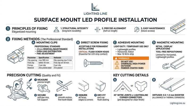
The fixing method for a surface mount LED profile determines three things: the long-term structural integrity of the installation, the precision of alignment over the full run length, and the ease of future access for maintenance or replacement. Every surface mount LED profile installation should be designed with the question: how will this be serviced in ten years? A profile that requires destructive removal for maintenance access is a poorly designed installation, regardless of how good it looks on day one.
Mounting clips — The professional standard
Mounting clips are separate fixing brackets that are screwed or nailed to the substrate at regular intervals, into which the aluminium profile snaps or slides. They are the professional standard for surface mount LED profile installation for several reasons: they allow the profile to be removed and reinstated without disturbing the substrate fixings, they distribute the mechanical load over multiple fixing points rather than relying on the profile’s own base stiffness and they allow fine adjustment of the profile position after the clips are fixed, before the profile is snapped in, ensuring perfectly straight runs over long distances.
| Parameter | Specification | Rationale |
|---|---|---|
| Clip spacing (standard) | 500 mm maximum centres | Prevents deflection of profile mid-span |
| Clip spacing (vibration environment) | 300 mm maximum centres | Prevents resonance loosening of clip retention |
| Clip spacing (outdoor/thermal cycling) | 400 mm maximum centres | Allows for differential thermal expansion |
| First clip position | Within 50 mm of each profile end | Prevents end-droop and end-cap misalignment |
| Fixings per clip | Minimum 2 (one each side) | Single-fixing clips can rotate under lateral load |
| Clip material | Zinc-plated steel or stainless (coastal/outdoor) | Galvanic compatibility with 6063 aluminium |
Direct screw fixing through the profile base
Direct screw fixing (where wood screws, self-tapping screws, or machine screws pass through pre-drilled fixing slots in the profile base into the substrate) is acceptable for permanent installations where the profile is unlikely to require removal during the installation’s service life.
When direct-fixing through the profile base, the screw head must not protrude above the base of the LED channel. Any protrusion will prevent the LED strip from sitting flat on the channel base, creating thermal bridging gaps and potential strip damage at the fixing point. Use countersunk screws with flush heads and confirm flush seating before installing the LED strip.
Adhesive mounting — When and when not to use it
Double-sided adhesive tape (either 3M VHB or equivalent-class acrylic transfer tape applied to the profile base) is acceptable for light-duty or temporary surface mount installations where the profile load (including LED strip and diffuser) does not exceed approximately 0.15 kg/m, and where the installation temperature will not regularly exceed 60°C at the adhesive interface. This limits adhesive-only mounting to: lightweight slim profiles (below 30 g/m), horizontal surface mounting on smooth flat substrates, indoor dry environments, and maximum strip power of approximately 10 W/m.
Adhesive-only mounting is not acceptable for: overhead (ceiling-mounted) surface profiles with any significant weight; high-power strips (above 10 W/m); outdoor applications (UV and thermal cycling degrade adhesive); smooth-painted or powder-coated substrate without mechanical key; any application where the profile failure would create a safety risk. In all of these situations, use mechanical fixings (clips or direct screws) as the primary fixing method, with adhesive as a supplementary alignment aid only.
Magnetic mounting for retail and display
For retail, display, and exhibition applications where LED profile positions need to be changed frequently, magnetic mounting systems (either magnetic tape on the profile base mating with ferrous steel backing strips on the display system, or steel profile bases mating with magnetic display panels) allow tool-free repositioning without any damage to either surface. Magnetic mounting is limited to horizontal or near-horizontal installations (within ±15° of horizontal) and profiles of less than 0.2 kg/m due to magnetic holding force limitations at elevated temperatures. For vertical retail profiles or any installation subject to vibration or incidental impact, additional mechanical retention is required.
Cutting surface mount LED profiles: tools, technique and precision
The quality of cut on an aluminium LED profile is immediately and permanently visible in the finished installation. A rough, burred, or non-perpendicular cut face makes it impossible for end caps to seat cleanly, prevents diffusers from fitting flush to the profile end, and creates a visible quality gap in the installation. Yet profile cutting is one of the most frequently rushed steps in LED installation with consequences that cannot be corrected without cutting a new profile piece.
Required tools and blade specification
| Tool | Required specification | Performance | Avoid |
|---|---|---|---|
| Compound mitre saw (preferred) | Non-ferrous metal blade, 80T minimum, negative rake (−5° to −10°), carbide-tipped | Clean, burr-free, perfectly square cuts. Consistent quality every time. 45° mitre capability. | Wood blades — coarse teeth tear aluminium. Ferrous metal blades — create heat and rough edges. |
| Table saw (alternative) | Fine-tooth non-ferrous blade, 80T+, negative rake | Very clean cuts. Good for production volumes. No angle capability without jig. | Any coarse-tooth blade. Dado blades. |
| Hacksaw (occasional use) | Fine-tooth blade, 24–32 TPI (teeth per inch), bimetal | Acceptable for site cuts with limited equipment. Quality varies with technique. | Standard 18 TPI hacksaw blades — too coarse. Worn blades of any specification. |
| Rotary deburring tool (mandatory) | Interchangeable blade type, HSS blades | Removes all burrs from cut faces in 30 seconds per cut | Needle files — too slow and inadequate for internal channel corners. |
| Soft-jaw vice or profile jig (mandatory) | Minimum 100 mm jaw width, rubber or nylon jaw faces | Holds profile securely without jaw marks on aluminium surface | Steel jaw vice without protection — marks visible anodised or powder-coat surface. |
Step-by-step cutting procedure
- Measure the required profile length precisely, accounting for end cap thickness (typically 1.5–3 mm per cap depending on profile type). If fitting end caps on both ends, subtract total end cap depth from the available profile length when planning the cut. Use a steel rule and fine-point scribe or silver pencil to mark the cut line on the profile base: never on the anodised or coated side surface.
- Secure the profile in a soft-jaw vice or profile-cutting jig with the cut mark visible above the vice jaws. Ensure the profile is fully supported over its length — unsupported profile overhanging the vice will flex during the cut, producing a non-square cut face. For profiles longer than 1.5 m, use a roller stand at each end to support the profile during handling.
- Set the mitre saw blade to exactly 90° and verify with a precision engineer’s square on the fence. Even 0.5° of fence error produces a visible gap at the profile end after a 2.4 m run. Zero the blade against the profile before committing to the cut by lowering the blade slowly to confirm the blade will pass exactly through the scribed mark.
- Make the cut in a single smooth downward motion, allowing the blade to cut at its rated speed. Do not force the blade — feed pressure is minimal with a fine-tooth blade in aluminium. A forced cut generates heat that forms burrs and may cause the profile to shift in the vice. For profiles wider than 30 mm, a second pass at slow feed rate may be needed to complete the cut cleanly.
- Deburr all cut faces immediately after every cut before touching any other surface. Use the rotary deburring tool on: (a) all four external edges of the cut face; (b) all four internal channel corners; (c) both inner channel lips where the diffuser will seat. The cut face must feel smooth to a gloved finger on all surfaces — any rough area will be visible at profile ends and will prevent clean end cap seating.
- Dry-fit the end cap before proceeding. The end cap should press onto the cut face with firm hand pressure and seat completely flush with the profile end on all sides simultaneously. Any gap, tilt, or resistance indicates a burr or non-square cut face that must be corrected before the profile is installed.
Mitre cuts for corner joins
When two surface mount profiles meet at an external corner (a 90° turn in the same plane), internal mitre cuts at 45° each produce a clean joint with minimal visible gap. The mitre saw blade is set to 45°, and both profiles are cut to complementary 45° angles that meet at the corner with the outside of the mitre at the finished corner position. The critical precision requirement: both cuts must be exactly 45° (not 44° or 46°) and both must be in exactly the same plane: any angular error appears as a visible gap at the front face of the joint. LightingLine.eu profiles are supplied with matching corner connector accessories that eliminate the need for mitre cuts in most standard configurations, providing a cleaner result than a mitre joint in most installation conditions.
Cutting the diffuser to match
Diffusers must be cut to match the aluminium profile length, but always 0.5–1.0 mm shorter than the aluminium profile. This critical tolerance allowance compensates for differential thermal expansion: polycarbonate and PMMA expand at 60–70 µm/m·°C (approximately 3× the aluminium rate of 23 µm/m·°C). A 2.4 m diffuser fitted flush to the profile end at 20°C installation temperature will expand by approximately 1.2 mm more than the aluminium during summer operation at 60°C: sufficient to bow the diffuser out of the channel lips if it cannot expand longitudinally.
Cut diffusers with sharp scissors (for polycarbonate diffusers thinner than 2 mm) or a fine-tooth hacksaw with the diffuser sandwiched between two pieces of masking tape to prevent cracking at the cut edge. Make the cut in a single smooth motion: multiple passes on polycarbonate create micro-cracking that propagates into the diffuser body over time. Deburr the cut ends of the diffuser lightly with fine sandpaper (400 grit) to remove any sharp edge that could scratch the profile channel lips during insertion.
Installing LED strip in surface mount profiles: the professional method
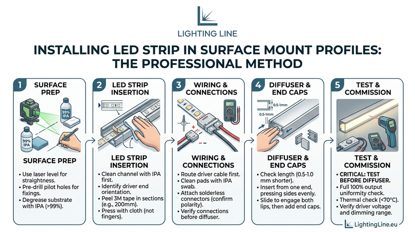
The installation sequence for a surface mount LED profile system is not complex, but each step must be completed in the correct order and to the correct standard. Shortcuts in installation sequence (particularly electrical testing before diffuser fitting, and surface preparation before LED strip adhesion) produce the majority of field failures and callbacks in LED profile installations. The following procedure describes the correct professional method that eliminates these failure modes.
Surface preparation
Before any profile or fixing is installed, the mounting surface must be prepared correctly. This step is almost universally skipped and is almost universally the cause of two specific failure modes: fixing screw pullout from unprepared substrates, and adhesive failure of the 3M backing tape on contaminated surfaces.
- Mark the profile centre line on the substrate using a chalk line or laser level. For runs longer than 1 m, a laser level is mandatory for acceptable straightness, chalk lines deflect under tension and produce visible bows in long profile runs. Mark the centre line with a 2B pencil or chalk, avoid graphite pencil on porous surfaces as it can bleed through white paint.
- Identify and mark all fixing points (clip positions or direct-screw positions) at the specified spacing (500 mm standard, 300 mm for heavy profiles or vibration environments). At each clip position, verify the substrate type and confirm the appropriate fixing for that substrate (pilot-drilled wood screw for timber, hammer-in Fischer anchor for plasterboard, rawlbolt for masonry, self-tapping screw for steel).
- Drill pilot holes at all fixing positions and install all fixings before any profile or clip is placed. Pre-drilling all fixings before profile installation prevents the common mistake of the drill slipping and damaging an already-installed profile.
- Degrease the substrate surface with IPA (99% isopropyl alcohol) along the full profile run length using a lint-free cloth. This applies to all surfaces (including new painted plasterboard and new timber) as all surfaces carry manufacturing oils, release agents, or wax compounds that reduce adhesive bond. Allow to dry for 60 seconds minimum.
Inserting the LED strip
- Clean the aluminium channel base with IPA before the LED strip is inserted. Manufacturing coolant residues and packaging contamination on the channel base reduce the adhesive bond of the LED strip 3M backing tape. Allow to dry fully.
- Determine the driver-connection end of the profile before inserting the strip. The LED strip must be oriented with the driver-connection end at the correct position in the profile (typically the end nearest the driver position). Inserting the strip in the wrong orientation requires removal and re-insertion which often damages the 3M tape and requires tape replacement before re-insertion.
- Peel the 3M backing tape progressively rather than all at once. For profiles up to 600 mm: peel the full length and insert in one operation. For profiles 600 mm–2,000 mm: peel the first 200 mm, press the strip into the channel mouth to register it, then peel 200 mm sections at a time while pressing the strip into the channel. For profiles above 2,000 mm: work with two installers one feeding the strip and peeling backing tape, one pressing the strip into the channel. Never stretch the strip during insertion: LED strip PCBs are dimensionally stable in compression but will crack solder joints under tensile stress.
- Press the strip firmly into the channel base using a clean lint-free cloth held flat against the PCB: not fingers, which concentrate force on individual LED packages and can crack their phosphor coating. Apply firm, even pressure over the full length of the strip, ensuring the PCB is in full contact with the aluminium channel base at every point. Any section not in full contact has a thermal bridge gap that will produce a hot spot visible as a brighter, dimmer, or colour-shifted section after hours of operation.
- Check the strip has not rotated within the channel. The LED strip must lie flat in the channel with the LEDs facing upward (toward the diffuser) and the PCB in full contact with the channel base. In wide channels, strips with narrow PCBs can twist if not guided correctly during insertion. Verify LED orientation with a brief test illumination before proceeding.
Wiring and connections
- Route the driver output cable to the profile connection point before the profile is fixed in its final position. The cable entry into the profile must be planned: either through a slot in the profile end, through a hole drilled in the profile base, or through a cable gap left at the profile-end-cap position. Running cables after the profile is fixed produces untidy surface runs or requires retrospective drilling that can crack the profile base.
- Clean the LED strip cut end with 99% IPA on a lint-free swab before attaching any connector. The cut end copper pads must be oxide-free and adhesive-free for reliable connector contact. Allow the IPA to dry completely. residual IPA under a connector accelerates copper oxidation.
- Attach the solderless connector to the LED strip cut end, confirming polarity (red = positive, black = negative or as marked on the specific driver and strip). Press the connector locking lever fully closed a partially closed connector will appear to work initially but will develop progressive contact resistance under thermal cycling. Test by gently pulling the strip: it should not pull out of a correctly closed connector.
- Connect the driver output to the connector and perform the electrical test at this stage: before the diffuser is fitted. This is a mandatory step. Testing after diffuser installation requires diffuser removal to access any fault. Any dark sections, dim sections, or colour inconsistencies visible at test stage must be diagnosed and corrected before the diffuser is fitted.
Fitting diffuser and end caps
- Confirm the diffuser length is 0.5–1.0 mm shorter than the profile. Measure with a steel rule before insertion.
- Insert the diffuser from one end, applying simultaneous pressure to both sides of the diffuser with thumb and forefinger. The diffuser should engage the inner channel lips at both sides simultaneously, inserting one side first and trying to pop the other side in will crack polycarbonate diffusers or permanently bow PMMA diffusers. If the diffuser requires more than light hand pressure to engage, there is a burr in one of the channel lips that must be removed before proceeding.
- Slide the diffuser along the full profile length, maintaining pressure to ensure both channel lip retentions are engaged. The diffuser should slide with light friction and no binding. If it binds at any point, stop, do not force it. Binding indicates either a burr, a section of channel deformed by handling, or a diffuser that is marginally oversize. Identify and correct before proceeding.
- Install end caps at both ends of the profile. End caps for LightingLine.eu profiles are supplied in two types: blank end caps (for sealed ends) and end caps with cable entry holes (for the driver-connection end). Press end caps onto the cut profile end with firm thumb pressure. A correctly fitting end cap will seat fully flush with the profile end face with a positive click or resistance-free slide to the fully seated position.
- If the profile run requires a cable exit mid-run (for power injection on runs above 8 m), use a profile section with a pre-drilled base hole at the power injection point, or carefully drill a 6 mm hole in the profile base using a sharp HSS twist drill at low speed with the drill perpendicular to the base. Drill speed above 500 rpm on aluminium produces heat that deforms the channel and requires deburring of the interior channel surfaces after drilling.
Testing and commissioning
- Full illumination test at 100% output: all sections of the profile should illuminate uniformly. Any dark section indicates a break in strip circuit (check cut point position and connector seating). Any dim section indicates high-resistance connector (clean and re-seat connector). Any colour variation indicates a strip batch colour binning issue (verify strip batch consistency) or a segment with reversed polarity (check strip polarity at connector).
- Uniformity assessment: at a 2 m viewing distance with diffuser installed, no individual LED positions should be visible through a frosted diffuser in a profile of 15 mm depth or greater. Through an opal diffuser at any depth, no individual LED positions should be visible. If dot visibility persists, verify diffuser specification against profile depth and LED strip technology as per the guidance in Section 5.
- Thermal check after 30 minutes operation: the external surface of the profile should feel warm (30–50°C above ambient is typical for a correctly loaded 14 W/m strip) but not hot. If the profile surface exceeds 70°C to the touch at full output, verify the strip power loading does not exceed the profile’s rated W/m capacity. A profile surface temperature above 70°C indicates either overloading or inadequate airflow around the profile.
- Driver test: verify driver output voltage is within ±1.5% of rated output under full load. Verify DALI addressing if DALI-2 drivers are specified. Verify dimming range is 0–100% without flicker or stepping. Record all test results in the commissioning documentation for the O&M manual.
Surface mount LED profile applications by room and sector
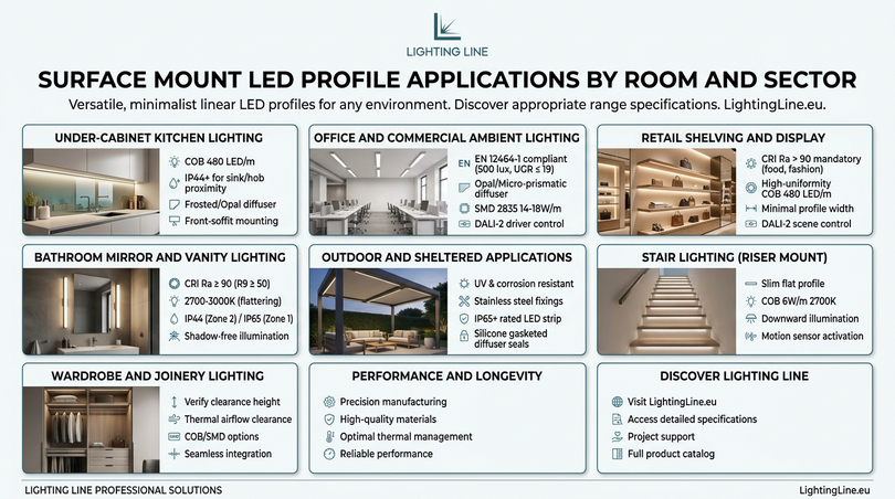
The surface mount LED profile is the most application-versatile profile type available: its compatibility with virtually any substrate and its minimal installation requirements allow it to be used in almost every lighting application that linear LED serves. The following sections describe the specific specification requirements for the most important application categories, with product references to the LightingLine.eu range for each.
Under-cabinet kitchen lighting
Under-cabinet kitchen lighting is the most common single application for surface mount LED profiles in the residential market and arguably the application where the quality difference between a cheap profile and a precisely manufactured profile is most immediately visible. The profile is at close viewing distance, the light falls on reflective kitchen splashbacks and worktops that act as mirrors for any dot or non-uniformity in the LED output, and the installation must survive the steam, grease, and occasional splash of a working kitchen environment for ten or more years.
The correct specification for under-cabinet surface mount kitchen profiles is: slim flat or standard U-channel, 8–12 mm channel width, COB LED strip (480 LED/m, CRI Ra > 90, 3000K, 24V, 6–9.6 W/m), frosted or opal diffuser, IP44 minimum for profiles within 600 mm of a sink or hob. The profile should be mounted at the front of the wall unit soffit, positioned to maximise worktop illumination and minimise direct glare to a person standing at the worktop. The front of the diffuser should be no more than 20 mm behind the front edge of the wall unit: positions further back create a shadow zone at the worktop front edge that is functionally and aesthetically unacceptable.
Office and commercial ambient lighting
Surface mount LED profiles for office ambient lighting must comply with EN 12464-1:2021 requirements for maintained illuminance (500 lux on working plane for general office), uniformity (Uo ≥ 0.60), and UGR (≤ 19 for display screen work environments). Surface mount profiles are the correct specification for office retrofit where ceiling void depth is insufficient for recessed profiles, and for concrete or exposed structure ceilings where recessing is structurally impractical.
The correct specification for office ambient surface mount profiles is: wide or standard U-channel, 15–20 mm channel width, SMD 2835 24V 14–18 W/m (120 LED/m), opal or micro-prismatic diffuser for UGR ≤ 19, white powder-coat finish for ceiling integration, with DALI-2 driver for daylight harvesting and occupancy control. Profiles should be run in parallel rows at spacing not exceeding 2.5× the mounting height above the working plane. For a 2.7 m ceiling office with 0.8 m working plane (effective height 1.9 m), maximum profile spacing is 4.75 m: typically 1.8–2.5 m centres for standard office lux levels.
Retail shelving and display
Retail shelf edge lighting is a specialised application of slim surface mount profiles where the goal is to highlight merchandise on shelves with an attractive warm glow that increases the perceived quality of the products displayed. CRI Ra > 90 is mandatory for any retail shelf lighting, CRI 80 strips make food, fabric, and cosmetics look flat, unappetising, and low-value. The profile must be as narrow and visually minimal as possible — ideally invisible below the shelf lip, with only the glow emerging.
The correct specification is: slim flat surface mount, 6–8 mm channel width, COB LED strip (480 LED/m, CRI Ra > 90, 3000K for fashion and food / 4000K for general retail, 24V, 6 W/m), transparent or frosted diffuser. The profile is positioned at the front underside of each shelf, aligned with the shelf front edge, with the diffuser facing downward toward the merchandise below. Connection to a DALI-2 driver with scene control allows the shelf lighting to be adjusted independently from the general ambient system, enabling promotional highlights, seasonal colour temperature adjustment, and closure-mode energy reduction.
Bathroom mirror and vanity lighting
Bathroom mirror lighting is among the most demanding surface mount profile applications in terms of CRI and colour temperature requirements. The primary function is to provide an accurate, shadow-free, flattering light for face illumination during grooming — which requires CRI Ra ≥ 90 (ideally Ra95+), R9 ≥ 50 to render skin tones correctly, a colour temperature of 2700–3000K (warmer temperatures are more flattering for the majority of skin tones), and a mounting position that delivers light from both sides of the mirror face rather than only from above (overhead-only mirror lighting creates unflattering shadows under the chin, nose, and eyes).
The IP specification depends on the zone: for profiles within 600 mm of a bath or shower (Zone 2 under BS 7671), IP44 is the minimum. For profiles within a shower enclosure or directly above a bath (Zone 1), IP65 minimum and IP67 is the professional specification for any profile that may be subject to direct water splash. All bathroom electrical connections must comply with Part P Building Regulations in the UK, and equivalent national regulations in EU member states.
Outdoor and sheltered external applications
Outdoor surface mount LED profiles must be specified with specific attention to UV resistance, corrosion resistance, and IP rating. Standard anodised aluminium profiles are acceptable for sheltered outdoor applications (under canopies, soffits, carports) in most European climates. For coastal environments or direct rain exposure, specify marine-grade powder coating or anodising with a minimum 25 µm anodic layer. All fixings in outdoor applications must be stainless steel — zinc-plated steel fixings create galvanic corrosion at the aluminium interface within 3–5 years in outdoor conditions.
The LED strip inside outdoor surface profiles must be rated IP65 minimum for sheltered positions and IP67 for any position subject to direct rain or condensation pooling. The diffuser seal must also be IP-rated, a standard friction-fit polycarbonate diffuser is not water-tight at IP65 and requires a silicone gasket seal at both channel lips for outdoor specification. End caps must be fitted with sealed cable glands at all cable entry points.
Stair lighting (surface profile on stair riser)
Surface mount LED profiles on stair risers provide wayfinding illumination that guides safe movement on stairs at night without requiring full-room illumination. The profile is mounted horizontally at the base of each riser (the vertical face of the step), directing light downward onto the tread below. The correct specification is a slim flat surface mount profile (to minimise protrusion from the riser face), 8–10 mm wide, COB LED strip at 6 W/m (2700K for residential, 3000K for commercial), frosted or opal diffuser, IP44 minimum for indoor stairs, IP65 for outdoor stairs. Motion sensor triggering is strongly recommended to extend LED lifetime and eliminate the need for manual switching on multi-flight stairs.
Wardrobe and joinery lighting
Interior joinery lighting (inside wardrobes, inside bookshelves, within display cabinets, under hanging rails) is an increasingly specified element of premium residential and retail fit-out, and surface mount slim profiles are the dominant specification. The key specification parameter for joinery applications is the profile height relative to the available clearance: a profile that cannot sit within the available recess in the shelf soffit or cabinet frame is impossible to install cleanly. Always confirm the available height clearance before specifying a profile type for joinery applications, and allow a minimum 5 mm clearance above the profile diffuser for thermal airflow.
Selecting the right LED strip for surface mount profiles
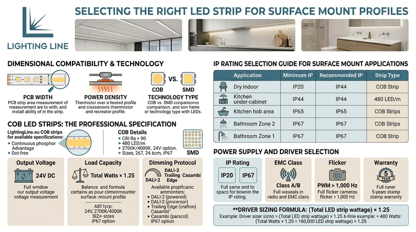
The LED strip specification must be matched to the surface mount profile in three dimensions: PCB width (must fit the channel without excess gap), power density (must not exceed the profile’s thermal capacity), and technology type (COB for shallow profiles; COB or SMD for deeper profiles; IP rating matched to application). A profile and strip that are incompatible in any of these dimensions will produce an installation that underperforms, fails prematurely, or (in the case of strip overloading) creates a thermal safety risk.
COB LED strips — The superior choice for surface mount
For any surface mount LED profile application where the profile is within normal viewing distance and the LED output is visible through the diffuser, COB LED strip is the professional specification. The continuous phosphor layer eliminates visible LED dots regardless of profile depth, diffuser type, or viewing angle. This allows surface mount profiles of minimal dimensions to be used without any optical compromise: the 3 mm PCB COB strip from LightingLine.eu achieves dot-free output in a 6 mm channel with a transparent diffuser, a combination impossible to replicate with any SMD strip technology.
LightingLine.eu COB strips for surface mount applications are available at CRI Ra > 90 (standard for all COB products), 480 LED/m, 24V, in 2700K and 4000K colour temperatures, on PCB widths of 3 mm, 5 mm, 8 mm, and 10 mm. The IP67 silicone tube format provides waterproof protection for bathroom, outdoor, and wet-area surface mount applications without any reduction in the optical or thermal performance of the COB strip.
SMD LED strips in surface profiles
SMD LED strips remain the correct specification for surface mount profiles in three situations: where RGB or RGBW colour changing is required (COB cannot produce independent RGB control), where tunable white dual-channel is required (COB does not support this configuration) and where very high lumen output is the primary specification driver in profiles of 18 mm depth or greater where dot suppression is achievable with a frosted diffuser.
IP ratings for surface mount applications
| Application | Minimum IP | Recommended IP | Strip type |
|---|---|---|---|
| Dry indoor — office, bedroom, retail | IP20 | IP20 | COB 5m 24V IP20 or SMD IP20 |
| Under-cabinet kitchen — general position | IP44 | IP44 | COB or SMD with silicone coat |
| Kitchen above hob or sink | IP65 | IP65 | SMD IP65 resin or COB IP67 silicone tube |
| Bathroom Zone 2 (>60cm from water) | IP44 | IP44 | COB IP44 or SMD IP44 |
| Bathroom Zone 1 (above/next to bath) | IP65 | IP67 | COB IP67 silicone tube |
| Outdoor sheltered (canopy, soffit) | IP65 | IP65 | SMD IP65 or COB IP67 |
| Outdoor exposed (direct rain) | IP67 | IP67 | COB IP67 silicone tube |
| Commercial kitchen / food production | IP65 | IP69K | SMD IP65/IP67 hygienic profile required |
Power supply and driver selection for surface mount LED systems
The LED driver is the power electronics module that converts mains AC voltage to the DC voltage required by the LED strip inside the surface mount profile. Correct driver specification is the component most commonly under-specified by installers who are otherwise careful about profile and strip selection. A correctly specified driver extends the LED strip lifetime, enables the full dimming range, and eliminates the flicker and instability that characterise cheap or incorrectly sized power supplies.
| Parameter | Correct specification | Why it matters |
|---|---|---|
| Output voltage | 24V DC (constant voltage) for all LightingLine.eu strips | Correct voltage for all SMD and COB products. Allows 7–10 m run length. |
| Load capacity | Driver rated wattage ≥ (total strip wattage × 1.25) | 80% derating rule: prevents electrolytic capacitor premature failure at full load. |
| Dimming protocol | DALI-2 for commercial, trailing edge (PWM) for residential, Casambi for retrofit | Protocol must be compatible with driver model, verify before specifying. |
| IP rating | IP20 for indoor enclosed, IP67 for surface mounting in damp areas | Driver is electrical equipment, IP rating must match installation environment. |
| EMC class | EN 55015 Class B for residential, Class A acceptable for industrial | Class B reduces conducted emissions that cause audible interference in audio systems. |
| Flicker | PWM frequency > 1,000 Hz, SVM ≤ 1.0 (EN 12464-1:2021 requirement) | Sub-1,000 Hz PWM causes camera flicker and may trigger photosensitive responses. |
| Warranty | 5 years minimum (Mean Well HLG series standard) | Driver lifetime must match LED strip L70 specification for maintenance-free period. |
Driver sizing formula: (total LED strip wattage in the circuit) × 1.25 = minimum driver rated output wattage. Example: a surface mount profile run of 8 m at 14 W/m = 112 W total strip load → minimum driver rating = 140 W → specify 150 W or 200 W driver (next standard sizes). Using a Mean Well HLG-150H-24B (150 W, 24V, DALI-compatible) at 112 W represents a 74% load factor — within the 80% derating limit and well within the thermal operating range for extended driver lifetime.
LightingLine.eu surface mount LED profile range
LightingLine.eu’s surface mount LED profile range represents the product of years of attending international LED and lighting trade fairs — including Hong Kong International Lighting Fair and Guangzhou International Lighting Exhibition — to source, evaluate, and select profiles that meet the technical and aesthetic standards that European architects, interior designers, and installers demand. Every surface mount profile in the LightingLine.eu range is Italian-designed, manufactured in 6063 T5 aluminium alloy, supplied with matched diffusers and end caps, and documented with full dimensional drawings and strip compatibility data. This is the curation that separates a professional product catalogue from a bulk price list.
Products in the surface mount range
| Product (SKU) | External dimensions | Max strip PCB | Special feature | Typical application | Catalogue link |
|---|---|---|---|---|---|
| 8×10 mm aluminium profile LLP-SL03-02 | 8 mm wide × 10 mm high | Up to 6 mm | Ultra-slim compact body: smallest surface profile in the range | Shelf edge, jewellery display, furniture reveal, under-cabinet minimal | View product → |
| 17×7 mm aluminium profile LLP-SL17-03 | 17 mm wide × 7 mm high | Up to 10 mm | Very low profile height: flat wide body ideal where ceiling clearance is minimal | Under-cabinet task, shelf soffit, wardrobe, display case | View product → |
| 17×15 mm aluminium profile LLP-SL05-03 | 17 mm wide × 15 mm high | Up to 10 mm | Balanced width/height ratio: good diffuser depth for dot suppression with SMD | Residential ambient, retail shelving, bathroom vanity, corridor | View product → |
| 18×6 mm flexible aluminium profile LLP-SL04-04-S2 | 18 mm wide × 6 mm high | Up to 10 mm | Flexible aluminium body: bends to follow curved surfaces and radii. Available in 2 m lengths. | Curved ceilings, arched recesses, furniture with curved edges, circular features | View product → |
| 21×25 mm aluminium profile LLP-SL01-01 | 21 mm wide × 25 mm high | Up to 12 mm | Deep high-output channel: 25 mm profile height gives excellent dot suppression and maximum thermal mass for high W/m strips | Office ambient, retail general, commercial high-output, kitchen ceiling | View product → |
| 27×7 mm aluminium profile LLP-SL07-05 | 27 mm wide × 7 mm high | Up to 12 mm | Very wide flat body: maximum PCB contact area for thermal management at minimal height | High-power strip in flat ceiling applications, under kitchen units with low clearance | View product → |
| 27×12 mm aluminium profile LLP-SL06-05 | 27 mm wide × 12 mm high | Up to 12 mm | Wide standard channel: ideal for 12 mm PCB strips at good diffuser depth, strong visual presence as a design element | Office retrofit surface ambient, industrial, feature ceiling detail | View product → |
| 36×26 mm aluminium profile LLP-SL02-06 | 36 mm wide × 26 mm high | Up to 20 mm | Largest surface profile: maximum channel width accommodates wide-PCB, dual or high-density strips, 26 mm height delivers outstanding dot suppression and thermal performance | Very high output commercial ambient, double-strip tunable white, signage backlight, industrial | View product → |
All LightingLine.eu surface mount profiles are available in silver anodised, white powder-coat, and black powder-coat finishes as standard. Multiple lengths are available for each model (2 m and 3 m, depending on profile). Matching diffusers (frosted, opal and transparent depending on profile type), end caps (blank and with cable entry), mounting clips, and corner connectors for 90° turns are available as accessories for every profile in the range.
Why LightingLine.eu surface profiles are the professional choice
The LightingLine.eu surface mount profile range is not differentiated from competitors solely on price or on the size of the catalogue. It is differentiated on the precision of the engineering and the depth of the specification support. Five specific technical characteristics distinguish LightingLine.eu surface mount profiles from the majority of alternatives available in the European market:
- 6063 T5 alloy with tolerance ±0.2–0.5 mm on channel width — channel width precision that ensures the specified LED strip sits correctly centred in the channel in full thermal contact with the base. Budget profiles routinely exceed ±1.0 mm tolerance, creating 2 mm gaps between the PCB edge and the channel wall.
- Diffusers tested to match each specific profile’s optical requirements — the frosted, opal and transparent diffusers supplied by LightingLine.eu are optically matched to the profile depth and channel geometry, not generic extrusions that happen to fit the channel. The lumen transmission and uniformity data in the catalogue is measured data, not manufacturer estimates.
- Full strip compatibility documentation in the B2B catalogue — every profile listing specifies the compatible LED strip PCB widths, the maximum W/m loading, and the minimum profile depth for dot-free performance with SMD strips. This eliminates the most common specification error in LED profile selection.
- Italian design heritage — the proportions, finish quality, and accessory integration of LightingLine.eu profiles reflect an industrial design approach rather than a purely engineering approach. Architects and interior designers specify LightingLine.eu profiles because they look right as well as performing correctly: a distinction that is immediately visible when the diffuser is installed and the room is occupied.
Specification guide for architects and contractors
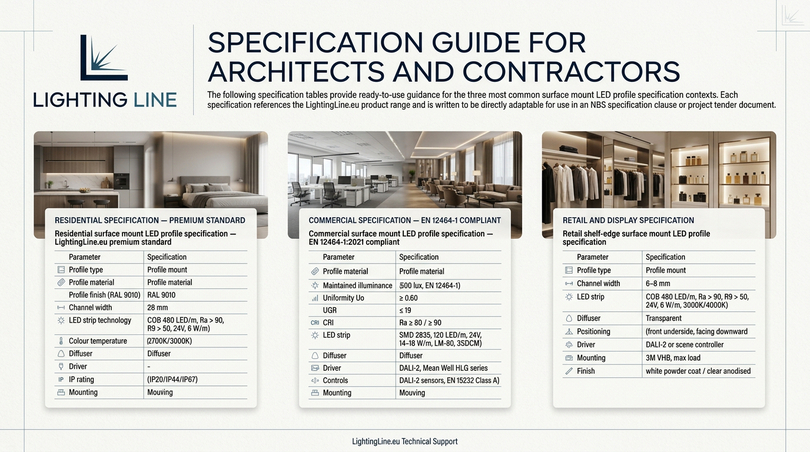
The following specification tables provide ready-to-use guidance for the three most common surface mount LED profile specification contexts. Each specification references the LightingLine.eu product range and is written to be directly adaptable for use in an NBS specification clause or project tender document.
Residential specification — Premium standard
| Parameter | Specification |
|---|---|
| Profile type | Surface mount aluminium LED profile — slim flat or standard U-channel as required by application |
| Profile material | 6063 T5 aluminium alloy, minimum wall thickness 1.2 mm |
| Profile finish | White powder coat (RAL 9010) or silver anodised as specified on drawings |
| Channel width | As required by LED strip PCB width — documented in project specification |
| LED strip technology | COB 480 LED/m, CRI Ra > 90, R9 > 50, 24V, 6 W/m — LightingLine.eu COB range |
| Colour temperature | 2700K (bedroom, living, hospitality) / 3000K (kitchen, bathroom) as drawing |
| Diffuser | Frosted polycarbonate for profiles ≥14 mm depth; opal for profiles <14 mm depth |
| Driver | Constant voltage 24V, minimum 80% rated load, trailing edge dimmable, 5 year warranty |
| IP rating | IP20 general; IP44 bathroom Zone 2; IP67 bathroom Zone 1 — silicone tube COB strip |
| Mounting | Steel mounting clips at 500 mm max. centres; stainless steel screws throughout |
Commercial and hospitality specification — EN 12464-1 compliant
| Parameter | Specification |
|---|---|
| Profile type | Surface mount aluminium LED profile — standard or wide U-channel |
| Profile material | 6063 T5 aluminium, 1.5 mm minimum wall thickness |
| Maintained illuminance | 500 lux on working plane (EN 12464-1, office) / as specified for other uses |
| Uniformity | Uo ≥ 0.60 on task area (EN 12464-1) |
| UGR | ≤ 19 for office / DSE work (EN 12464-1) |
| CRI | Ra ≥ 80 (minimum); Ra ≥ 90 recommended for hospitality and retail |
| LED strip | SMD 2835, 120 LED/m, 24V, 14–18 W/m, LM-80 certified, 3SDCM — LightingLine.eu SMD range |
| Diffuser | Opal or micro-prismatic for UGR ≤ 19 compliance |
| Driver | DALI-2 constant voltage 24V, minimum 75% rated load, 5 year warranty — Mean Well HLG series |
| Controls | DALI-2 with DALI Part 303 occupancy sensor and DALI Part 304 daylight sensor — EN 15232 Class A |
| Mounting | Steel mounting clips at 500 mm max. centres |
Retail and display specification
| Parameter | Specification |
|---|---|
| Profile type | Surface mount slim flat — minimum protrusion below shelf |
| Channel width | 6–8 mm (to accept 5 mm COB PCB) |
| LED strip | COB 480 LED/m, CRI Ra > 90, R9 > 50, 24V, 6 W/m, 3000K (fashion/food) or 4000K (general retail) |
| Diffuser | Transparent (COB strips — dot-free without frosting) |
| Positioning | Front underside of shelf, within 10 mm of front shelf edge, LEDs facing downward |
| Driver | DALI-2 or scene controller with preset scenes for promotional/ambient/closed modes |
| Mounting | Adhesive 3M VHB (for shelf soffit, maximum 0.15 kg/m load) or clip-mounting for heavier profiles |
| Finish | White powder coat (to blend with shelf soffit) or clear anodised (for visible installation) |
Maintenance, cleaning and long-term performance
One of the most significant practical advantages of surface mount LED profiles over recessed alternatives is maintenance accessibility. The surface mount profile (with its diffuser, LED strip, and driver all accessible without ceiling modification) allows every component to be inspected, cleaned, or replaced independently, in minutes, without any disturbance to the surrounding surfaces. This accessibility advantage should be factored into the whole-life cost analysis of any LED lighting system, as it significantly reduces the maintenance cost per annum compared to recessed systems where diffuser access requires specialist access equipment and plastering trade involvement.
Cleaning
Surface mount aluminium LED profiles should be cleaned with a slightly damp lint-free microfibre cloth. Never use solvent-based cleaners on anodised or powder-coated aluminium: solvents degrade the surface coating and reduce corrosion resistance. For diffusers, clean with an antistatic polycarbonate cleaner or a damp cloth, avoid abrasive materials that scratch the diffuser surface and reduce light transmission by creating micro-scratches that scatter transmitted light. In commercial kitchens and food production environments, clean hygienic profiles with food-safe degreaser in accordance with the HACCP cleaning schedule, pressure washing at temperatures above 60°C requires IP69K-rated profiles and diffusers.
Diffuser replacement
Surface mount profile diffusers can be replaced without removing the profile from the surface. Simply remove the end caps at one end of the profile, slide the old diffuser out of the channel lips, slide the new diffuser in from the open end, and replace the end caps. The entire operation takes approximately 2 minutes per metre of profile, requires no tools, and does not require any work at the driver or electrical connections. This makes diffuser replacement for yellowing, cracking, or intentional aesthetic change an entirely practical maintenance activity over the profile’s 20+ year service life.
LED strip replacement
LED strip replacement in surface mount profiles requires: removal of end caps and diffuser, disconnection of the LED strip from the driver output, removal of the LED strip from the channel, cleaning of the channel base with IPA and installation of the new strip as per the Section 9 procedure. The entire process for a single 2.4 m surface mount profile takes approximately 20–30 minutes. L70 lifetime at 50,000 hours (at 8 hours/day operation) = 17 years between strip replacements: for most installations, strip replacement will never be required within the building’s refurbishment cycle.
FAQ — Professional answers about surface mount LED profiles
What is a surface mount LED profile?
What is the difference between a surface mount LED profile and a recessed LED profile?
What LED strip width fits in a surface mount LED profile?
What fixings are used for surface mount LED profiles?
What diffuser should I use with a surface mount LED profile?
How do I cut a surface mount aluminium LED profile?
Can surface mount LED profiles be used outdoors?
What is the thermal performance of a surface mount LED profile?
What is the correct mounting clip spacing for a surface mount LED profile?
How do I prevent the LED strip from showing through a frosted diffuser?
Why should I specify LightingLine.eu surface mount profiles instead of cheaper alternatives?
The surface mount LED profile decision is a quality decision
The surface mount LED profile is the most commonly installed LED lighting component in Europe and (because of that ubiquity) the one about which the most shortcuts and false economies are made. The guide you have just read is the comprehensive counterargument to every one of those shortcuts: evidence-based, specification-precise, and grounded in the real consequences that poor surface mount profile choices produce in the field, on the ceiling, and in the client relationship.
The decisions you now know how to make correctly: whether to specify COB or SMD strip for your profile depth, which diffuser type achieves dot-free performance at the available profile height, what channel width ensures full thermal contact between the LED strip PCB and the aluminium heat sink, how to cut profiles cleanly and deburr them correctly; how to size the driver to achieve 80% maximum load for extended lifetime and how to install the strip in the correct sequence to prevent the most common field failures. These are not marginal improvements: they are the difference between an installation that will still look excellent in 2040 and one that will require replacement in 2029.
LightingLine.eu’s Italian-designed surface mount LED profile range is the physical expression of everything this guide describes: 6063 T5 aluminium, elongated fixing slots, matched diffuser optics, complete B2B specification support, and design quality that architects and interior designers across Europe choose when the installation needs to reflect the quality of the overall project. The range is available for immediate B2B ordering in the LightingLine.eu online catalogue, with full dimensional drawings, strip compatibility data, and DXF files for design documentation.
This article was developed with the support of artificial intelligence and subsequently reviewed, corrected, and validated by the LightingLine.eu technical team, which guarantees its reliability and compliance with official sources.