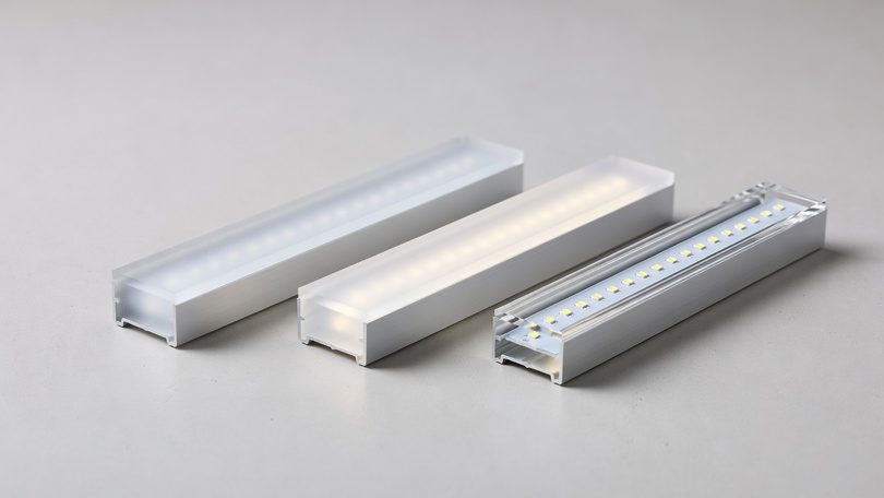
The diffuser is the component that determines whether your LED strip installation looks professionally designed or immediately reveals itself as a DIY compromise. It controls glare, uniformity, lumen output, colour temperature perception, and UGR compliance. Yet it is specified almost entirely on guesswork in most projects: “frosted” because it sounds right, or “clear” because it looks brighter. This guide replaces guesswork with data — transmission percentages, dot suppression depths, UGR impact figures, material comparisons, CCT shift values, and application-specific specifications. Drawn from the LightingLine.eu technical team’s experience supplying aluminium LED profiles and matched diffusers to architects, installers and lighting designers across Europe.
In this article…
2. What is a LED profile diffuser? Function, materials and atructure
3. The four main LED diffuser types: complete technical guide
4. Light transmission data: how much light does each diffuser absorb?
5. Dot suppression: which diffuser eliminates LED hotspots?
6. UGR and glare control: which diffuser achieves EN 12464-1 compliance?
7. Colour Temperature shift through LED diffusers
8. Polycarbonate vs PMMA: full technical comparison
9. Diffuser selection by application: the complete specification guide
10. Profile depth and diffuser matching: the critical relationship
11. How to cut LED profile diffusers correctly
12. Diffuser maintenance, yellowing and replacement
13. LightingLine.eu diffuser range — Matched to every surface profile
14. Quick-reference specification guide
15. FAQ — Professional answers about LED profile diffusers
16. Specify the diffuser first, not last
Why the diffuser is the most under-specified component in LED profile systems
In the typical specification of an aluminium LED profile system, the diffuser receives approximately thirty seconds of attention. The aluminium profile is selected with care: internal width, external height, alloy grade, finish. The LED strip is specified with some rigour: COB or SMD, wattage per metre, CRI, colour temperature, IP rating. The driver is sized, dimming protocol is selected. And then someone reaches the diffuser field in the specification document and writes “frosted” because that is the word that instinctively appears when the concept of “LED profile cover” enters the mind. This is how most LED profile diffuser specifications are made and it is why a surprising proportion of finished LED lighting installations look worse than they should.
The diffuser is not a passive transparent cover. It is an active optical component that shapes, modifies, and controls the light output of the LED strip in ways that are measurable, predictable, and consequential for the finished result. The wrong diffuser choice sacrifices up to 55% of the lumen output you paid for. It can produce a UGR value of 28 in an office space that EN 12464-1:2021 requires to be below 19. It can make a 3000K LED strip appear perceptibly warmer or cooler than specified. It can allow individual LED dots to remain visible through a polycarbonate cover in a prestigious hotel installation, creating a result that every guest notices and nobody defends. Or it can do the opposite: a correctly specified opal diffuser on a shallow surface profile transforms an SMD strip that would otherwise look like a string of bright points into a seamless, luminous line that makes the profile appear to glow from within.
This guide documents every decision you need to make about LED profile diffusers with the technical precision that professional specification demands. Transmission percentages measured, not estimated. Dot suppression data by profile depth and strip technology. UGR impact quantified. Colour temperature shift characterised. Material properties compared. Cutting technique specified. Maintenance requirements documented. By the time you finish reading, you will specify diffusers from knowledge rather than from convention and your installations will look demonstrably better as a result.
2. What is a LED profile diffuser? Function, materials and structure
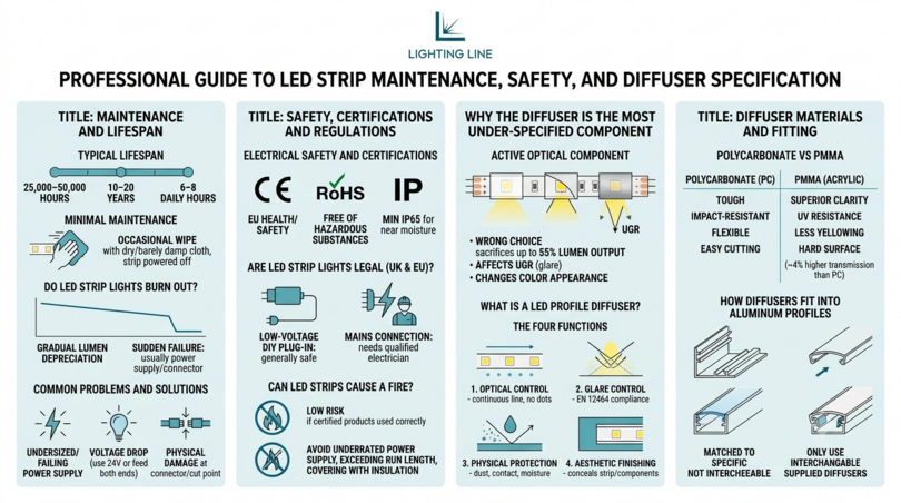
The LED profile diffuser (also called the LED strip cover diffuser, LED channel diffuser, or LED strip lighting cover) is the translucent or transparent cover that clips into the channel lips of an aluminium LED profile, enclosing the LED strip inside and controlling the optical output of the combined fitting. It is an extruded component, typically made from polycarbonate (PC) or polymethyl methacrylate (PMMA), whose cross-section matches the internal geometry of the profile channel so that it seats securely and can be installed and removed without tools.
The four functions of the LED strip cover diffuser
A correctly specified LED profile diffuser performs four distinct and equally important functions:
| Function | What it does | Consequence of wrong diffuser |
|---|---|---|
| 1. Optical control (dot suppression) | Scatters light from discrete LED point sources to create a continuous, uniform luminous surface | Individual LED positions visible as bright dots, unprofessional appearance that cannot be corrected without replacing diffuser |
| 2. Glare control (UGR reduction) | Reduces luminance of the diffuser surface to levels that do not cause discomfort to observers — essential for EN 12464-1 compliance | UGR exceeds standard limits, office lighting fails compliance; occupants experience eye strain and visual fatigue |
| 3. Physical protection | Protects the LED strip PCB and LED packages from dust, incidental contact, moisture (in sealed/IP-rated systems), and UV degradation | Dust accumulation on exposed LEDs reduces lumen output by 5–15% over 3–5 years, contact damage destroys LEDs |
| 4. Aesthetic finishing | Creates a clean, linear appearance concealing the LED strip components and providing the luminous surface that defines the aesthetic of the fitting | The LED strip, PCB, connectors and wiring visible: defeats the purpose of using a precision aluminium profile |
Polycarbonate vs PMMA (Acrylic): material overview
The two materials used for LED profile diffusers have distinct optical and mechanical properties that make each more suitable for specific applications. Polycarbonate (PC) is tougher, more impact-resistant, and more flexible: it can be bent around tight radii without cracking, making it the material of choice for flexible aluminium profiles and curved applications. It cuts easily with scissors without cracking, and is easier to handle and install without damage. PMMA (acrylic) has superior optical clarity, better UV resistance (critical for outdoor and skylight-adjacent applications), lower yellowing rate over time, and a harder surface that is more resistant to superficial scratching. PMMA has approximately 4% higher light transmission than PC at equivalent formulations. Full material comparison is in Section 8.
How diffusers fit into aluminium LED profiles
LED profile diffusers are extruded to match the internal geometry of specific profile families. The cross-section of a diffuser designed for a 21×25 mm surface profile differs from one designed for a 27×12 mm profile: they share the same general U-shape but differ in the width of the flat section, the angle of the side walls, and the geometry of the retention lips that engage with the channel lips of the aluminium profile. Diffusers are not interchangeable between different profile families only diffusers manufactured to match the specific profile geometry will seat correctly, seal cleanly at the end caps, and transmit light in the designed direction.
LightingLine.eu supplies matched diffusers for every profile in the range, documented in the online B2B catalogue with the specific profile reference each diffuser is designed for. When ordering profiles and diffusers separately, always verify compatibility against the profile reference number: never assume that a diffuser of the same nominal width as the profile channel will fit.
3. The four main LED diffuser types: complete technical guide
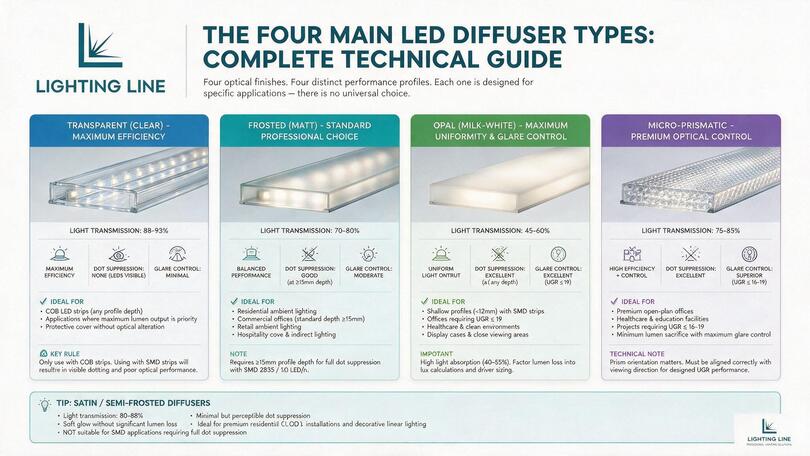
Within the polycarbonate and PMMA material categories, LED profile diffusers are manufactured with four distinct optical finishes, each producing a different combination of light transmission, dot suppression, and glare control. These four types are not interchangeable design preferences: each has a specific performance profile that makes it correct for certain applications and wrong for others. Understanding the technical distinctions between them is the foundation of correct diffuser specification.
Transparent (clear) diffuser — Maximum efficiency
The transparent or clear diffuser is an unmodified extrusion of optically clear polycarbonate or PMMA with no scattering agents, coatings, or surface treatments. Light passes through it with 88–93% transmission: the highest of any diffuser type. It provides structural protection of the LED strip and a clean appearance but performs essentially no optical modification of the light output. Whatever the LED strip produces, the transparent diffuser delivers — including, for SMD strips, the visible individual LED positions that in most applications constitute an unacceptable result.
The transparent diffuser is the correct specification in exactly one situation with significant practical importance: COB LED strips at any profile depth. COB’s continuous phosphor layer produces inherently dot-free light regardless of diffuser proximity, so the transparent cover delivers the maximum possible lumen output from the COB strip while providing the protective and finishing functions of the diffuser. Specifying an opal diffuser over a COB strip wastes 40–55% of the lumen output for zero optical benefit — it is the most common and most expensive misspecification in COB LED installations.
For every COB LED strip installation, specify a transparent or lightly frosted diffuser. The COB phosphor layer already achieves complete dot suppression — additional scattering from a frosted or opal diffuser produces nothing but lumen loss. LightingLine.eu COB strips at 480 LED/m produce a perfectly uniform, dot-free luminous line through a transparent cover at any profile depth.
Frosted (matt) diffuser — The standard professional choice
The frosted diffuser is the most widely specified LED profile cover diffuser in the European professional market and for good reason: it delivers an excellent balance between light transmission (70–80%) and optical quality for the majority of applications. The frosted surface is created by either a micro-textured surface finish applied during extrusion (creating microscopic surface irregularities that scatter transmitted light) or a chemical etching process applied post-extrusion (producing a softer, more uniform scattering pattern).
The frosted diffuser’s dot suppression performance depends critically on the distance between the LED strip and the diffuser: the profile depth. At depths of 15–18 mm with SMD 2835 strips at 120 LED/m, a frosted diffuser achieves good dot suppression with individual LED positions imperceptible to observers at normal viewing distances. At depths below 12 mm, the scattering distance is insufficient for the frosted texture to fully blend the light cones of adjacent SMD LEDs, and individual positions remain visible — particularly at oblique viewing angles. This relationship is fully documented in Section 5.
The frosted diffuser is the correct default specification for: residential ambient lighting (surface and recessed profiles); commercial office surface profiles at standard depths (15 mm+); retail ambient where the profile is above normal head height; hospitality cove and indirect lighting; and any application where the profile is not in close viewing proximity and a moderate lumen penalty (20–30%) is acceptable.
Opal (milk-white) diffuser — Maximum uniformity and glare control
The opal diffuser is a heavily loaded extrusion containing TiO₂ (titanium dioxide) pigment particles dispersed throughout the PC or PMMA matrix. These particles scatter transmitted light with very high efficiency: so efficiently that a 3 mm thick opal diffuser makes the light from even the most widely spaced SMD strip appear completely uniform, with no visible variation in luminance across the entire diffuser surface. The price of this optical perfection is the most significant lumen penalty of any standard diffuser type: 40–55% of the LED strip’s output is absorbed within the opal material and re-emitted as diffuse light in all directions, with only 45–60% transmitted in the intended forward direction.
This lumen penalty is a real design constraint that must be factored into lux calculations. An installation designed around 1,800 lm/m from a 24V SMD 2835 strip at 14 W/m will deliver approximately 900–1,080 lm/m through an opal diffuser: barely more than 50% of what the strip produces. To achieve the same lux level as a frosted diffuser installation, either the strip wattage must be increased (typically by 50–70%) or the profile spacing must be reduced. This has a direct impact on installed cost, energy consumption, and driver sizing.
Despite this penalty, the opal diffuser is not merely acceptable , it is mandatory in several critical applications: any surface mount profile shallower than 12 mm with SMD strips, any office luminaire needing to achieve UGR ≤ 19, healthcare environments where flicker-free uniform illumination is required, any application where the profile is at close viewing range (below head height, at eye level or in display case lighting) and pendant direct/indirect office profiles where the downward-facing diffuser is directly visible from workstations.
Micro-prismatic diffuser
The micro-prismatic diffuser is an engineered optical component that achieves higher light transmission than opal (75–85%) while delivering better glare control than frosted (the combination that professional office lighting specification demands). Its surface is structured with microscopic prismatic facets (typically 50–200 µm pitch) that redirect light rays rather than simply scattering them. This allows the micro-prismatic diffuser to control the angular distribution of light output limiting the high-angle luminance that causes UGR issues while maintaining good forward efficiency.
The micro-prismatic diffuser is the specification of choice for premium open-plan office, healthcare, and education applications requiring UGR ≤ 16–19 with minimum lumen sacrifice. It is more expensive than frosted or opal alternatives and requires more careful specification because the prismatic pattern direction matters: the facets must be oriented correctly relative to the viewing direction to achieve the designed UGR performance.
Satin and semi-frosted diffusers
Between the fully transparent and the frosted standard, there is a family of lightly modified diffusers (satin, semi-frosted, or lightly etched finishes) that achieve light transmission of 80–88% with minimal but perceptible dot suppression. These are appropriate for COB installations where a slight softening of the linear glow is desired without the lumen penalty of a full frosted finish, and for premium residential applications where the diffuser surface is intended to be seen as a softly luminous element rather than simply a protective cover. They are not suitable as a substitute for frosted or opal in SMD installations where dot suppression is required.
4. Light transmission data: how much light does each diffuser absorb?
Light transmission is the percentage of incident light that passes through the diffuser in the designed direction. It is the single most important quantitative parameter for diffuser specification because it directly determines the lumen output of the finished luminaire — and therefore the lux levels delivered to the illuminated surface. Failing to apply the diffuser transmission factor in lux calculations is the most common error in LED profile lighting design, and it invariably results in installations that are 20–55% dimmer than the design specification intended.
Full transmission comparison table
Light transmission measured at normal incidence, 555 nm peak sensitivity (photopic), 2 mm material thickness:
| Diffuser type | Transmission range | Central value | Lumen loss | Dot suppression (SMD, 14mm depth) | UGR impact |
|---|---|---|---|---|---|
| Transparent / Clear | 88–93% | 91% | 7–12% | None — all LED positions visible | None — highest UGR |
| Satin / Semi-frosted | 80–88% | 84% | 12–20% | Minimal — dots still visible at close range | Slight reduction |
| Micro-prismatic | 75–85% | 80% | 15–25% | Good at ≥ 12 mm depth | Best per lumen — EN 12464 UGR ≤ 16–19 |
| Frosted / Matt | 70–80% | 75% | 20–30% | Good at ≥ 15 mm, moderate at < 12 mm | Moderate reduction |
| Opal / Milk-white | 45–60% | 52% | 40–55% | Excellent at any depth ≥ 6 mm | Significant — best for UGR control |
Impact on lux calculations — Worked examples
The diffuser transmission factor must be applied to the LED strip lumen output before any lux calculation is performed. The lux formula is: E = (N × F × UF × MF × DT) / A, where DT is the diffuser transmission factor (0.91 for transparent, 0.75 for frosted, 0.52 for opal, etc.).
| Diffuser | Transmission | Delivered lm/m | Total lm | Calculated lux | vs transparent |
|---|---|---|---|---|---|
| Transparent | 91% | 1,638 lm/m | 16,380 lm | ~172 lux | Baseline |
| Satin | 84% | 1,512 lm/m | 15,120 lm | ~159 lux | −8% |
| Micro-prismatic | 80% | 1,440 lm/m | 14,400 lm | ~151 lux | −12% |
| Frosted | 75% | 1,350 lm/m | 13,500 lm | ~142 lux | −17% |
| Opal | 52% | 936 lm/m | 9,360 lm | ~98 lux | −43% |
This worked example makes the opal diffuser’s impact visually stark: specifying opal instead of transparent on a 10m run of SMD strip delivers 43% fewer lux to the working plane — the difference between a comfortable 172 lux and a deficient 98 lux. If the target is 300 lux (residential ambient) or 500 lux (office), the entire strip wattage, driver sizing, and profile spacing calculation must be recalculated from scratch when the diffuser changes. This is why diffuser specification is an integral part of the photometric design process, not an afterthought applied to an already-complete specification.
The lumen penalty: when opal costs you more strip
Consider a commercial office installation requiring 500 lux (EN 12464-1 minimum) on a 200 m² open-plan floor at 2.8 m ceiling height. The initial specification uses a 14 W/m SMD 2835 strip at 24V producing 1,800 lm/m, with a frosted diffuser (75% transmission = 1,350 effective lm/m). After lux calculation, 85 m of profile is required. Now the electrical engineer requests a change to opal diffuser for UGR compliance. At 52% transmission = 936 effective lm/m, the same lux target now requires 122 m of profile — 44% more profile, 44% more LED strip, 44% more drivers. The combined additional material cost is typically €800–1,200 for this installation size. This is the hidden cost of changing diffuser specification after the photometric design is complete: which is why diffuser choice must be made at the start of the design process, not at the finish.
5. Dot suppression: which diffuser eliminates LED hotspots?
Dot suppression (the elimination of visible individual LED positions through the diffuser) is the optical function that most directly determines the perceived quality of an LED profile installation. A linear LED fitting that shows visible dots is immediately identified as low-quality, amateur, or incorrectly specified — even by observers who have no technical knowledge of LED lighting. It is the visual equivalent of seeing the individual pixels on a low-resolution screen: the eye immediately and instinctively recognises it as inadequate.
Dot suppression with SMD LED strips by profile depth
With SMD LED strips, dot suppression is governed by the mixing distance: the space between the LED chip and the diffuser surface within which adjacent light cones can overlap and blend into a continuous illuminated field. The greater the profile depth, the more mixing distance available, and the less scattering the diffuser needs to provide to achieve dot-free output. This relationship determines which diffuser is correct for any given profile depth with any given SMD strip density.
| Profile depth (LED to diffuser) | SMD 60 LED/m | SMD 120 LED/m | SMD 168 LED/m | Required diffuser (120 LED/m) |
|---|---|---|---|---|
| Below 8 mm | All dots clearly visible | All dots clearly visible | All dots visible | Opal — mandatory, dots visible through frosted |
| 8–12 mm | Dots clearly visible | Dots visible at oblique angles | Minimal dot visibility | Opal — frosted inadequate for close viewing |
| 12–15 mm | Dots visible at <1m viewing | Dots marginal with frosted | Dot-free with frosted | Frosted acceptable for overhead, opal for close-range |
| 15–20 mm | Dots visible in direct view | Dot-free with frosted | Dot-free with frosted or satin | Frosted — standard specification |
| 20–25 mm | Marginal with opal | Dot-free with frosted or satin | Dot-free with any diffuser | Frosted, satin if premium finish desired |
| Above 25 mm | Dot-free with frosted | Dot-free with any diffuser | Dot-free with any diffuser | Any diffuser — transparent acceptable with 168 LED/m |
Why COB LED strips change everything
COB (Chip-on-Board) LED strips fundamentally alter the dot suppression calculus. Because COB deposits hundreds of micro-scale chips beneath a continuous, uninterrupted phosphor layer, there are no gaps between point sources: light is emitted from every millimetre of the strip’s length simultaneously. The result is a strip that appears, through any diffuser at any profile depth, as a continuous luminous surface with no visible variation in luminance. There is no minimum profile depth for dot-free COB output. A 3 mm PCB COB strip in a 6 mm channel with a transparent cover is dot-free. The same is emphatically not true of any SMD strip.
This COB property has a direct and important consequence for diffuser specification: with COB strips, the diffuser type should be selected entirely on the basis of glare control and transmission, with dot suppression eliminated as a consideration. Transparent for maximum output; lightly frosted if surface glare from the diffuser itself needs to be reduced; opal only if very low-luminance output (such as step lighting or indicator applications) is required. Specifying opal over COB for dot suppression purposes is a specification error that wastes 40–55% of the lumen output for a function the COB strip already performs itself.
Dot suppression reference table: technology × profile depth × diffuser
| LED technology | Profile depth | Transparent | Frosted | Opal |
|---|---|---|---|---|
| COB (any density) | Any depth | ✅ Dot-free | ✅ Dot-free | ✅ Dot-free (unnecessary lumen loss) |
| SMD 168 LED/m | Below 12mm | ❌ Dots visible | ⚠️ Marginal | ✅ Dot-free |
| SMD 168 LED/m | 12–18mm | ❌ Dots visible | ✅ Dot-free | ✅ Dot-free |
| SMD 168 LED/m | Above 18mm | ⚠️ Near-dot-free | ✅ Dot-free | ✅ Dot-free |
| SMD 120 LED/m | Below 12mm | ❌ Dots clearly visible | ❌ Dots visible at close range | ✅ Dot-free |
| SMD 120 LED/m | 12–15mm | ❌ Dots visible | ⚠️ Marginal at close viewing | ✅ Dot-free |
| SMD 120 LED/m | 15–20mm | ❌ Dots visible | ✅ Dot-free | ✅ Dot-free |
| SMD 120 LED/m | Above 20mm | ⚠️ Marginal at oblique | ✅ Dot-free | ✅ Dot-free |
| SMD 60 LED/m | Below 20mm | ❌ All dots clearly visible | ❌ Dots visible | ✅ Dot-free |
| SMD 60 LED/m | 20–30mm | ❌ Dots visible | ⚠️ Marginal with frosted | ✅ Dot-free |
| SMD 60 LED/m | Above 30mm | ❌ Dots visible | ✅ Dot-free | ✅ Dot-free |
If you cannot achieve the required profile depth for dot-free SMD performance, there are two solutions: switch to COB LED strip (dot-free at any depth, any diffuser) or specify opal diffuser (dot-free at any depth with any SMD density). Both solutions have trade-offs: COB has slightly lower efficacy than high-density SMD while opal has 40–55% lumen penalty. In most professional applications, the COB switch is the better answer because it preserves lumen output while achieving the optical result.
6. UGR and glare control: which diffuser achieves EN 12464-1 compliance?
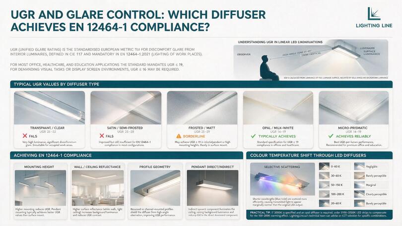
UGR (Unified Glare Rating) is the standardised European metric for discomfort glare from interior luminaires, defined in CIE Publication 117 and embedded as a mandatory compliance parameter in EN 12464-1:2021 (Lighting of Work Places). For most office, healthcare, and education applications, the standard mandates UGR ≤ 19. For very demanding visual tasks or display-screen environments, UGR ≤ 16 may be required. The diffuser type is the single most influential variable in the UGR performance of an LED profile luminaire, more so than profile geometry, ceiling height, or room proportions.
Understanding UGR in linear LED installations
UGR is calculated from the luminance of the luminaire surface as seen by an observer at the specified reference point, weighted by the solid angle subtended by the luminaire and the background luminance of the space. For linear LED profiles, the critical variable is the luminance of the diffuser surface in the high-angle zone (65–85° from vertical), the angles at which a ceiling-mounted luminaire is seen by a seated office worker, and at which discomfort glare is most strongly experienced. The diffuser type directly controls this high-angle luminance.
| Diffuser type | Typical UGR range | EN 12464-1 UGR ≤ 19? | EN 12464-1 UGR ≤ 16? | Notes |
|---|---|---|---|---|
| Transparent / Clear | 26–32 | ❌ Fails | ❌ Fails | Very high luminance, significant discomfort glare. Unsuitable for any occupied work area. |
| Satin / Semi-frosted | 23–28 | ❌ Fails | ❌ Fails | Improved but insufficient for EN 12464-1 compliance in most configurations. |
| Frosted / Matt | 19–25 | ⚠️ Borderline — depends on geometry | ❌ Fails | May achieve UGR ≤ 19 in indirect/pendant or at high mounting heights. Rarely achieves it in surface mount. |
| Opal / Milk-white | 14–20 | ✅ Typically achieves | ⚠️ Borderline | Standard specification for UGR ≤ 19 compliance in offices and healthcare. |
| Micro-prismatic | 13–19 | ✅ Achieves reliably | ✅ Achievable | Best UGR-per-lumen performance. Recommended for premium office and education. |
UGR by diffuser type and profile configuration
The UGR values in the table above are typical for surface-mounted profiles in a standard room geometry (4H × 8H EN 12464-1 reference room). They are influenced by several additional factors:
- Mounting height: higher mounting reduces UGR. A frosted diffuser in a pendant profile at 2.0 m below a 3.5 m ceiling achieves lower UGR than the same diffuser surface-mounted at ceiling level.
- Background luminance: higher room surface reflectances (white walls, light-coloured ceiling) increase background luminance, which reduces the UGR contrast and therefore the calculated UGR value.
- Profile geometry: profiles with recessed channels (where the diffuser sits below the profile body) achieve lower UGR than flush-diffuser profiles because the aluminium body shields the diffuser from high-angle observation.
- Pendant direct/indirect: the indirect upward component of a direct/indirect pendant profile illuminates the ceiling, raising background luminance and reducing UGR for the direct downward component, a further advantage of pendant configurations over surface-mount for UGR-sensitive applications.
Achieving UGR ≤ 19 for office EN 12464-1 compliance
The practical specification pathway to EN 12464-1 UGR ≤ 19 compliance for linear LED profile lighting in office environments:
- Specify opal or micro-prismatic diffuser as standard for any surface-mounted or recessed profile in an open-plan office, hot-desk, DSE workstation, or collaborative area. Frosted diffusers are not reliably compliant in most surface-mount configurations.
- For pendant profiles, frosted diffuser may be acceptable if a photometric calculation with the specific luminaire data confirms UGR ≤ 19 at all reference points. Obtain the LTD (luminous intensity distribution) file from the profile and strip supplier and run the UGR calculation in DIALux or Relux before committing to frosted specification.
- For recessed profiles, the aluminium housing shields the diffuser at high angles, improving UGR. A frosted diffuser in a recessed profile typically achieves UGR of 18–22 depending on geometry — a photometric calculation is required to confirm compliance.
- Micro-prismatic diffuser should be specified wherever UGR ≤ 16 is required (demanding visual tasks, fine manufacturing, surgical preparation areas) — opal rarely achieves this consistently without sacrificing excessive lumen output.
- Document the UGR compliance in the lighting design report with reference to the photometric calculation and the specific diffuser reference used. EN 15193-1 audits require this documentation.
7. Colour Temperature shift through LED diffusers
Every LED profile diffuser produces a measurable shift in the apparent colour temperature of the LED strip it covers. This shift arises from selective scattering: diffuser materials preferentially scatter shorter wavelengths (blue, violet) more efficiently than longer wavelengths (red, yellow), causing the transmitted light to appear marginally warmer than the direct output of the LED strip. For most residential and hospitality applications, this shift is desirable: it adds a subtle warmth to a 3000K strip that makes the light feel more comfortable and flattering. For applications where precise colour temperature repeatability is required, it must be measured and compensated at the specification stage.
| Diffuser type | CCT shift (Kelvin) | Direction | Perceptible at 3000K? | Perceptible at 4000K? |
|---|---|---|---|---|
| Transparent / Clear | 0–20 K | None / negligible | No | No |
| Satin | 30–60 K warmer | Warmer | Barely | No |
| Frosted | 50–150 K warmer | Warmer | Marginal — barely perceptible | Barely |
| Opal | 100–200 K warmer | Warmer | Yes — visible in side-by-side comparison | Marginal |
| Micro-prismatic | 20–60 K warmer | Warmer | No | No |
The practical specification implication: if the project specifies 3000K as the delivered colour temperature, and an opal diffuser is required, order 3100–3150K LED strips to compensate for the 100–200K warming effect of the opal. Without this correction, a 3000K strip through an opal diffuser delivers an apparent 2820–2900K: perceptibly warmer, and inconsistent with the specification intent. LightingLine.eu’s technical team can advise on CCT selection for specific diffuser and strip combinations on request.
This shift also explains why LED strip installations appear inconsistent when different profile depths are used on the same project with the same strip and the same nominal diffuser type: the thicker diffuser material absorbs more short wavelengths, producing a slightly warmer apparent colour temperature. For projects using multiple profile types, verify that the diffuser material thickness and formulation is consistent across all profile families or use COB strips (whose broad-spectrum phosphor emission is less susceptible to selective diffuser scattering than the narrower spectra of some SMD chips).
8. Polycarbonate vs PMMA: full technical comparison
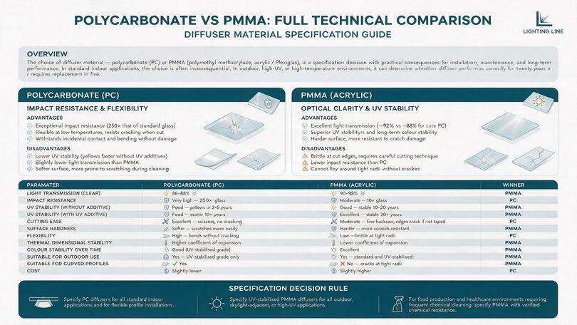
The choice of diffuser material polycarbonate (PC) or PMMA (polymethyl methacrylate, commonly called acrylic or Plexiglas) is a specification decision with practical consequences for installation, maintenance, and long-term performance. Most installers accept whichever material the profile supplier provides without considering the alternatives. In most standard indoor applications, the choice is inconsequential. In outdoor, high-UV, or high-temperature environments, it can determine whether the diffuser performs correctly for twenty years or requires replacement in five.
Polycarbonate (PC) — Impact resistance and flexibility
Polycarbonate is a thermoplastic known for exceptional impact resistance (250× that of standard glass), high clarity, and flexibility at low temperatures. In the LED profile diffuser context, its advantages are: resistance to cracking when cut, flexibility allowing it to follow the slight curves of aluminium profiles that have been bowed by installation forces; and resilience to incidental contact damage. Its disadvantages are: lower UV stability than PMMA (it yellows faster in UV-exposed installations unless UV stabilisers are added to the formulation), a slightly lower light transmission than equivalent PMMA and a softer surface more susceptible to surface scratching from cleaning.
PMMA (Acrylic) — Optical clarity and UV stability
PMMA offers superior UV stability, higher light transmission (approximately 92% vs 88% for clear PC), better colour stability over time, and a harder surface more resistant to superficial scratch damage. Its disadvantages are brittleness at cut edges (requires more careful cutting technique than PC), lower impact resistance, and inability to flex around tight radii without cracking. For any outdoor or UV-exposed installation, PMMA is the correct material specification: UV-stabilised PMMA diffusers maintain their optical properties for 15–25 years in direct UV exposure, compared to UV-unstabilised PC which may begin to yellow visibly within 3–5 years.
Material comparison table
| Parameter | Polycarbonate (PC) | PMMA (Acrylic) | Winner |
|---|---|---|---|
| Light transmission (clear) | 86–88% | 90–93% | PMMA |
| Impact resistance | Very high — 250× glass | Moderate — 10× glass | PC |
| UV stability (without additive) | Poor — yellows in 2–5 years | Good — stable 10–20 years | PMMA |
| UV stability (with UV additive) | Good — stable 10+ years | Excellent — stable 20+ years | PMMA |
| Cutting ease | Excellent — scissors; no cracking | Moderate — fine hacksaw; edges crack if not taped | PC |
| Surface hardness | Softer — scratches more easily | Harder — more scratch-resistant | PMMA |
| Flexibility | High — bends without cracking | Low — brittle at tight radii | PC |
| Thermal dimensional stability | Higher coefficient of expansion | Lower coefficient of expansion | PMMA |
| Colour stability over time | Good (UV-stabilised grade) | Excellent | PMMA |
| Suitable for outdoor use | Yes — UV-stabilised grade only | Yes — standard and UV-stabilised | PMMA |
| Suitable for curved profiles | ✅ Yes | ❌ No — cracks at tight radii | PC |
| Cost | Slightly lower | Slightly higher | PC |
Specification decision rule: specify PC diffusers for all standard indoor applications and for flexible profile installations. Specify UV-stabilised PMMA diffusers for all outdoor, skylight-adjacent, or high-UV applications. For food production and healthcare environments requiring frequent chemical cleaning, specify PMMA with a verified chemical resistance specification — many cleaning agents attack PC surfaces, causing haze and micro-cracking.
9. Diffuser selection by application: the complete specification guide
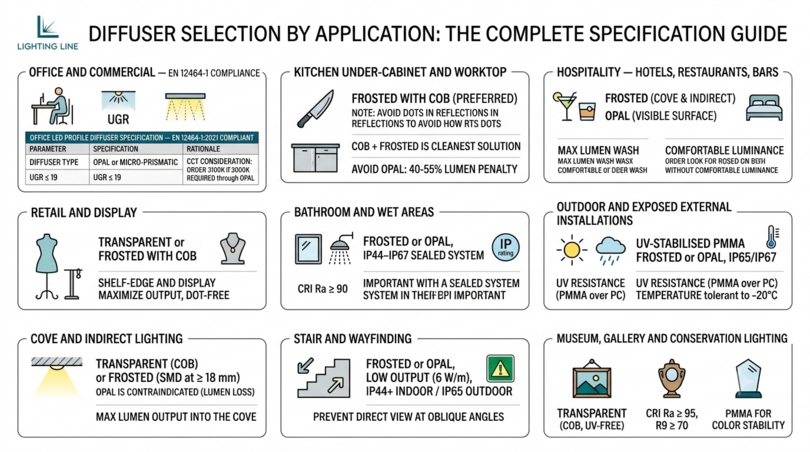
The following specifications are the LightingLine.eu standard recommendations for each major application category. Each recommendation is based on the combination of optical performance, compliance requirements, lumen efficiency, and practical installation considerations for that specific use case.
Office and commercial — EN 12464-1 compliance
| Parameter | Specification | Rationale |
|---|---|---|
| Diffuser type | Opal or micro-prismatic | UGR ≤ 19 requirement (EN 12464-1 for DSE workspaces) |
| Material | PC (standard) or PMMA (premium) | Indoor — UV stability not critical |
| LED strip compatibility | COB or SMD 2835 120 LED/m at ≥ 15 mm profile depth | Dot-free through opal at any depth; frosted acceptable at ≥ 15 mm only |
| CCT consideration | Order 3100K strip if 3000K delivered result is required through opal | Opal shifts apparent CCT by 100–200K warmer |
| UGR verification | Photometric calculation required before final specification | Surface mount vs recessed vs pendant affects UGR significantly |
Kitchen under-cabinet and worktop
Specification: frosted diffuser with COB strip (preferred) or frosted with SMD at ≥ 15 mm depth. The kitchen worktop is a reflective surface that acts as a light meter for any non-uniformity in the strip: dots visible through the diffuser are doubled by the worktop reflection. COB strip with a frosted or transparent diffuser is the cleanest solution. Avoid opal in kitchen under-cabinet applications: the 40–55% lumen penalty defeats the purpose of task lighting in a cooking environment. IP44 minimum for profiles within 600 mm of a sink or hob, verify the diffuser seal against the profile channel lips is IP-rated to match the strip.
Hospitality — Hotels, restaurants, bars
Specification: frosted (cove and indirect) or opal (visible surface-mount fittings in dining areas). Cove lighting (where the profile is concealed in a ceiling recess and light washes upward) uses the frosted or transparent diffuser most effectively: maximum lumen output washes the ceiling, creating the warm glow that defines hospitality cove lighting. For visible surface profiles in dining or lounge areas at or below seated eye level, opal is the correct choice: the luminance must be comfortable for diners seated directly below or adjacent to the profile. In bar back-lighting applications where the profile is deliberately part of the visual display, transparent with COB strip is the specification that creates the brightest, most dramatic linear glow.
Retail and display
Specification: transparent or frosted with COB strip for shelf-edge and display lighting. Retail shelf-edge LED profiles are typically slim (6–10 mm channel width) and at minimal profile depth: exactly the conditions that require COB for dot-free output. The transparent diffuser maximises the lumen output directed downward onto merchandise, while COB’s continuous phosphor provides the dot-free luminous line that makes the product display look designed rather than improvised. For general retail ambient in surface profiles at ceiling height, frosted with SMD 168 LED/m at ≥ 15 mm depth provides adequate dot suppression with good lumen efficiency.
Bathroom and wet areas
Specification: frosted or opal, IP44–IP67 sealed system. Bathroom mirror lighting requires accurate colour rendering (CRI Ra ≥ 90, R9 ≥ 50) and flattering colour temperature (2700–3000K): both of which are best achieved with COB strips, whose broad-spectrum phosphor maintains colour accuracy through any diffuser. For Zone 1 applications (within 600 mm of water), the diffuser and profile must form a sealed IP65 or IP67 assembly: the diffuser must be sealed to the profile with a silicone gasket at both channel lips and sealed at both end caps. A loose friction-fit diffuser is not IP-rated regardless of the profile’s nominal IP specification.
Outdoor and exposed external installations
Specification: UV-stabilised PMMA frosted or opal, sealed IP65/IP67 system. Outdoor diffusers are subjected to daily UV irradiation, thermal cycling (−20°C to +60°C in Northern European climates), rain, airborne pollutants, and in coastal environments, salt spray. Standard PC diffusers without UV stabiliser will show visible yellowing within 2–3 years in direct outdoor exposure. Specify UV-stabilised PMMA as the diffuser material for all outdoor applications. The diffuser seal at both channel lips must be IP65 minimum (silicone gasket or overmoulded seal) for sheltered positions and IP67 for direct rain exposure. Cut ends of outdoor diffusers must be sealed with clear neutral-cure silicone before end caps are fitted.
Cove and indirect lighting
Specification: transparent (COB) or frosted (SMD at ≥ 18 mm depth). In cove and indirect applications, the diffuser surface itself is not visible to the room occupants — only the light it projects onto the ceiling or upper wall is seen. This changes the specification logic: dot suppression on the diffuser surface is irrelevant (because the diffuser is not seen), but the angular distribution of light emerging from the diffuser determines how evenly the ceiling is washed. For cove lighting, the primary diffuser requirement is maximum lumen output directed into the cove: transparent with COB is the optimal specification. Opal is contraindicated for cove applications: the 40–55% lumen loss delivers a dim, underwhelming indirect wash when a bright, warm ceiling glow was the design intent.
Stair and wayfinding
Specification: frosted or opal, low output (6 W/m), IP44 minimum indoor / IP65 outdoor. Stair LED profiles serve a safety function first and an aesthetic function second. The diffuser must prevent any direct view of the LED strip at the viewing angles of a descending staircase user: typically 30–60° from horizontal, where the strip is seen directly into the face of the stair riser profile. At these oblique angles, frosted diffusers with SMD strips at shallow depths (below 12 mm, as most stair profiles are) will show visible dots. Specify either COB with frosted/transparent, or opal with any SMD strip, for stair profile applications.
Museum, gallery and conservation lighting
Specification: transparent (COB, UV-free strip), CRI Ra ≥ 95, R9 ≥ 70. Museum and gallery lighting for artwork display requires the highest colour rendering achievable and zero UV emission (UV damages organic pigments, textiles, and paper). For the diffuser specifically: transparent or very lightly frosted PMMA provides the maximum light output directed at the artwork, with the broadest possible spectral bandwidth — opal’s heavy scattering slightly compresses the spectral distribution, which is measurable in very high-precision colour rendering applications. Specify PMMA (not PC) for gallery diffusers — its higher colour stability over decades ensures consistent colour transmission as the installation ages.
10. Profile depth and diffuser matching: the critical relationship
The profile depth (the internal distance from the LED strip PCB surface to the inside face of the diffuser) is the geometric parameter that determines the effectiveness of any diffuser in suppressing LED dot visibility for SMD strips. It is the single most important installation variable for diffuser performance and the one that is most commonly either unknown to the specifier or treated as irrelevant. Getting this relationship wrong produces the most visible quality failure in LED profile lighting: visible LED dots in a finished installation that cannot be corrected without a complete strip change.
Minimum profile depth by strip technology and diffuser type
| LED strip technology | Transparent | Frosted (standard) | Opal | Micro-prismatic |
|---|---|---|---|---|
| COB 480 LED/m (any PCB width) | Any depth ✅ | Any depth ✅ | Any depth ✅ | Any depth ✅ |
| SMD 2835 — 168 LED/m | Not achievable ❌ | ≥ 12 mm | ≥ 6 mm | ≥ 10 mm |
| SMD 2835 — 120 LED/m (standard) | Not achievable ❌ | ≥ 15 mm | ≥ 6 mm | ≥ 12 mm |
| SMD 2835 — 60 LED/m | Not achievable ❌ | ≥ 25 mm | ≥ 6 mm | ≥ 20 mm |
| RGBW (multi-chip, 60 LED/m) | Not achievable ❌ | ≥ 30 mm (colour mixing) | ≥ 15 mm (colour mixing) | ≥ 25 mm |
Note for RGBW strips:the minimum depth for colour mixing (elimination of colour separation between R, G, B and W chips) is greater than for luma dot suppression alone. RGBW strips at shallow profile depths show distinct coloured sections rather than a blended white output — opal diffuser at 15 mm depth minimum is the practical minimum for RGBW to produce an acceptable white output.
Why getting this wrong is the most visible mistake in LED lighting
When a specifier installs a frosted diffuser on a surface profile of 10 mm internal depth (such as the LightingLine.eu 8×9 mm profile) with an SMD 120 LED/m strip, the result is a luminous cover through which every individual LED position is clearly visible as a bright oval (approximately 5 cm apart) with darker zones between them. This appearance is immediately obvious to any observer who looks at the profile. It cannot be corrected by adjusting the driver output, changing the dimming level, or modifying the installation in any other way. The only correction is to remove the SMD strip and install a COB strip, or to replace the frosted diffuser with an opal diffuser.
This failure mode is the most common quality complaint in LED profile installations. It occurs because the specification process treats strip and diffuser as independent choices rather than as a matched system defined by the profile depth. The LightingLine.eu B2B catalogue prevents this error by documenting the recommended strip technology, profile depth, and diffuser type for each specific profile: creating a system specification rather than a parts list.
11. How to cut LED profile diffusers correctly
Cutting the LED profile diffuser correctly is the last technical step before the profile is complete and ready for commissioning. Incorrect cutting (wrong length, cracked edges, rough cuts that prevent end cap seating) produces a visible quality failure at the most scrutinised point of the installation: the profile end. The investment of two extra minutes in correct diffuser cutting produces a result that distinguishes a professional installation from an amateur one at the precise point where the client’s eye is drawn.
Why diffusers must be cut shorter than the profile
The thermal expansion coefficients of polycarbonate and PMMA are approximately 60–70 µm/m·°C. The thermal expansion coefficient of aluminium (6063 T5) is approximately 23 µm/m·°C. For a 2.4 m installation operating between 20°C installation temperature and 55°C operating temperature (a typical ceiling profile surface temperature with a 14 W/m strip):
- Aluminium profile expands by: 2.4 × 23 × 35 = 1.93 mm
- PC/PMMA diffuser expands by: 2.4 × 65 × 35 = 5.46 mm
- Differential expansion: 3.53 mm — the diffuser grows 3.5 mm more than the profile over a 35°C temperature rise.
If the diffuser is cut flush to the profile length and fitted with end caps at both ends, this 3.5 mm differential expansion has nowhere to go. The diffuser will buckle out of the channel lips at the mid-point, or the end caps will be pushed off their seating, or the diffuser edge will crack against the end cap. Cutting the diffuser 0.5–1.0 mm shorter than the profile at installation temperature provides a 1 mm expansion gap at each end, which is sufficient for the differential expansion of installations up to approximately 3 m length in the temperature range described.
Cutting technique by material
| Material | Tool | Technique | Avoid |
|---|---|---|---|
| PC (Polycarbonate) — thin (≤ 2 mm) | Sharp scissors (not craft scissors — use dressmaker’s or florist’s scissors with long, sharp blades) | Single smooth closing action, perpendicular to diffuser length. The diffuser should cut cleanly with no cracking, as PC is very flexible. | Blunt scissors, deform rather than cut. Serrated scissors, leave rough edge. Repeated partial cuts. |
| PC (Polycarbonate) — thick (> 2 mm) | Fine-tooth hacksaw, 24–32 TPI, bimetal blade | Apply masking tape on both faces of the diffuser at the cut line before marking. Cut through tape, the tape prevents micro-cracking at the cut edge. | Angle grinder (too aggressive). Coarse blades. Cutting without tape backing on thick PC. |
| PMMA (Acrylic) | Fine-tooth hacksaw, 24–32 TPI, or score-and-snap (thin PMMA only) | Apply masking tape on both faces. Cut with smooth, consistent forward strokes, allowing the blade to cut without forced downward pressure. Deburr lightly with 400-grit paper. | Scissors on PMMA, crack edges immediately. Circular saw blades (too fast, creates heat). Impact cutting. |
Fitting and seating the diffuser
- Verify the cut length before attempting to insert the diffuser. Measure against the installed profile: the diffuser should be 0.5–1.0 mm shorter than the visible profile length for indoor installations, 1.5–2.0 mm shorter for outdoor.
- Inspect the cut ends for any sharp edges, cracks, or deformations. PMMA diffusers in particular can develop micro-cracks at cut edges that propagate over time under thermal cycling stress. Lightly sand with 400-grit and wipe clean with a dry cloth.
- Inspect the profile channel lips for any burrs from profile cutting. A burr in the channel lip will prevent the diffuser from seating flat, causing it to bow along its length. Remove any burr with a rotary deburring tool before attempting diffuser insertion.
- Insert the diffuser from one end, applying simultaneous lateral pressure to both sides of the diffuser with thumb and forefinger. Both channel lip retentions must engage simultaneously — never try to lever one side in after the other, as this cracks both PC and PMMA diffusers.
- Slide the diffuser along the full profile length with light hand pressure. The diffuser should slide with gentle friction and no binding. If it binds or bows at any point, do not force it — identify the obstruction (burr, channel deformation, or diffuser too wide) and correct it before proceeding.
- Fit end caps last, confirming they seat flush with the profile end and engage securely on all four sides simultaneously.
12. Diffuser maintenance, yellowing and replacement
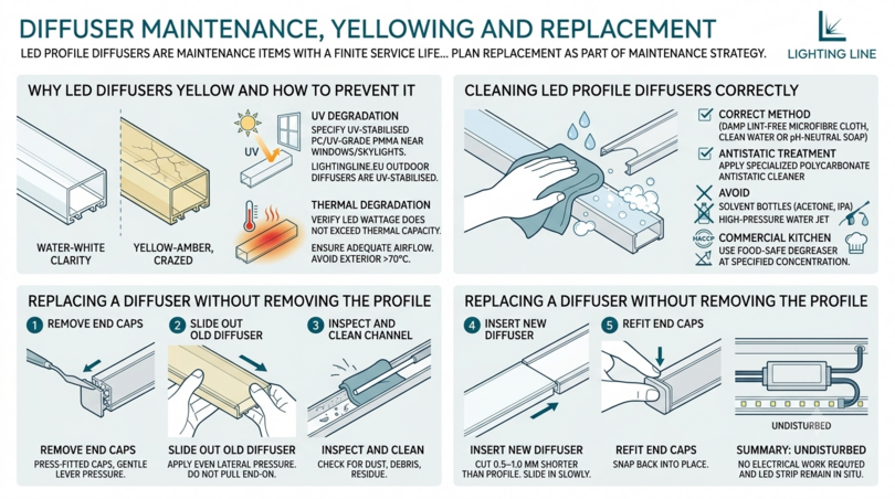
LED profile diffusers are maintenance items with a finite service life that, in most installations, significantly exceeds the practical refurbishment cycle of the building. However, in environments with elevated UV exposure, chemical cleaning, or extreme temperatures, diffuser condition should be periodically inspected and replacement planned as part of the building’s lighting maintenance strategy.
Why LED diffusers yellow and how to prevent it
Diffuser yellowing (a progressive shift from water-white clarity to yellow-amber) is caused by two distinct mechanisms:
UV degradation: UV radiation from sunlight (or from inadequately filtered LED sources in some applications) breaks down the polymer chains in PC and PMMA, producing chromophores that absorb blue light and transmit yellow. This manifests as a visible yellow cast that is most obvious when the LED strip is off and the diffuser is examined against a white background. Prevention: specify UV-stabilised PC or UV-grade PMMA for any installation within 3 m of a window, skylight, or any UV source. LightingLine.eu specifies UV-stabilised materials for all outdoor-rated diffusers.
Thermal degradation: sustained operation at temperatures above the diffuser’s rated maximum continuous temperature (typically 70°C for standard PC, 80°C for PMMA) accelerates polymer breakdown, producing both yellowing and surface crazing. Prevention: verify that the LED strip wattage does not exceed the aluminium profile’s thermal capacity, and ensure adequate airflow around the profile. A surface temperature above 70°C on the exterior of the profile suggests the LED strip is overloading the profile’s thermal management — reduce the strip wattage or upgrade to a higher-capacity profile.
Cleaning LED profile diffusers correctly
Routine cleaning of LED profile diffusers requires attention to both the cleaning agent and the method:
- Correct method: damp lint-free microfibre cloth, lightly moistened with clean water or a dilute (0.1%) solution of pH-neutral soap. Wipe along the diffuser length with light, even pressure. Dry immediately with a second dry cloth.
- Antistatic treatment: PC diffusers develop a static charge that attracts airborne dust. An antistatic polycarbonate cleaner (available from specialist plastics suppliers) applied after cleaning and allowed to dry creates a surface treatment that significantly reduces dust reattachment.
- Avoid: solvent-based cleaners (acetone, MEK, IPA) on PC surfaces, these dissolve the surface, creating permanent hazing. Abrasive cloths or sponges, micro-scratches reduce diffuser transmission by 3–8% and scatter transmitted light, reducing uniformity. High-pressure water jets — these force water under the diffuser channel lips, compromising the sealing of IP-rated systems.
- Commercial kitchen diffusers: in HACCP environments, clean with food-safe degreaser at the concentration specified in the cleaning schedule. Verify chemical resistance of the diffuser material against the specific cleaning agents used, some industrial degreasers attack both PC and PMMA at concentrations above 5%.
Replacing a diffuser without removing the profile
One of the most significant practical advantages of aluminium LED profile systems over integrated LED luminaires is the ability to replace individual components — including the diffuser — without disturbing the overall installation. Diffuser replacement on a surface mount profile requires no tools and takes approximately 2 minutes per metre:
- Remove the end caps at both ends of the profile section. Most LightingLine.eu end caps are press-fitted and can be removed by inserting a thin flat tool (palette knife or credit card) in the gap between the end cap and the diffuser face and applying gentle lever pressure.
- Slide the old diffuser out from one end, applying the same even lateral pressure used during installation. Do not pull the diffuser straight out end-on, this can bow or crack it, and fragments inside the channel may damage the LED strip.
- Inspect the channel interior for dust accumulation, debris from the old diffuser, or adhesive residue from the LED strip. Clean with a dry lint-free cloth on a flexible rod (a drumstick or wooden dowel works well for standard channel widths).
- Cut the new diffuser to length (0.5–1.0 mm shorter than the aluminium profile) and insert following the procedure in Section 11.3.
- Refit end caps. No electrical work is required — the LED strip, driver, and all wiring remain undisturbed throughout the diffuser replacement.
13. LightingLine.eu diffuser range — Matched to every surface profile
LightingLine.eu supplies matched diffusers for every aluminium LED profile in the range: surface, recessed, corner, cove, stair, and pendant profiles. LightingLine.eu diffusers are designed and manufactured to the specific cross-sectional geometry of each profile family, not generic extrusions that approximate a fit. This ensures correct channel lip engagement, flush end cap seating, and the designed optical performance for each profile type.
| Profile | Profile dimensions | Internal depth | Compatible LED strip | Recommended diffuser | Catalogue link |
|---|---|---|---|---|---|
| 8×10 mm (LLP-SL03-02) | 8 mm W × 10 mm H | ~6 mm | COB up to 6 mm PCB | Transparent or frosted — COB required for dot-free at this depth | View → |
| 17×7 mm (LLP-SL17-03) | 17 mm W × 7 mm H | ~5 mm | COB up to 10 mm PCB | Transparent or frosted — COB mandatory, SMD produces visible dots at 5 mm depth with any diffuser | View → |
| 17×15 mm (LLP-SL05-03) | 17 mm W × 15 mm H | ~12 mm | COB or SMD up to 10 mm PCB | Frosted (with COB) or opal (with SMD 120 LED/m) — 12 mm depth is marginal for frosted/SMD, opal provides certainty | View → |
| 18×6 mm flexible (LLP-SL04-04-S2) | 18 mm W × 6 mm H | ~4 mm | COB up to 10 mm PCB (flexible) | Transparent or frosted — COB required, flexible profile demands PC diffuser (PMMA cracks at bend radii) | View → |
| 21×25 mm (LLP-SL01-01) | 21 mm W × 25 mm H | ~22 mm | COB or SMD up to 12 mm PCB | Frosted (any strip) or opal (for UGR ≤ 19) — 22 mm depth gives dot-free frosted with SMD 120 LED/m, micro-prismatic for office compliance | View → |
| 27×7 mm (LLP-SL07-05) | 27 mm W × 7 mm H | ~5 mm | COB up to 12 mm PCB | Transparent or frosted — very shallow depth (5 mm): COB mandatory for dot-free output | View → |
| 27×12 mm (LLP-SL06-05) | 27 mm W × 12 mm H | ~10 mm | COB or SMD up to 12 mm PCB | Frosted (with COB) or opal (with SMD) — at 10 mm, frosted works for COB, SMD needs opal for reliable dot suppression | View → |
| 36×26 mm (LLP-SL02-06) | 36 mm W × 26 mm H | ~23 mm | COB or SMD up to 20 mm PCB | Any diffuser type — 23 mm depth allows frosted, opal, micro-prismatic or transparent (with COB) for any application, micro-prismatic for office UGR compliance at this large scale | View → |
All LightingLine.eu diffusers are supplied in the correct length for the profile (2 m or 3 m matching the profile order), in PC standard material for indoor applications.
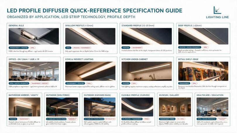
14. Quick-reference specification guide
The following consolidated table provides the complete diffuser specification decision in one reference — organised by the three primary specification drivers: application, LED strip technology, and profile depth.
| Application / Context | LED strip | Profile depth | Specify diffuser | Do NOT use | Key reason |
|---|---|---|---|---|---|
| Any application, any profile depth | COB (any PCB width) | Any | Transparent or frosted | Opal (unless very low luminance needed) | COB is dot-free through any diffuser — opal wastes 40–55% of lumens with no benefit |
| Shallow profile (below 12 mm) | SMD (any density) | < 12 mm | Opal | Frosted, transparent | Only opal suppresses dots at depths below 12 mm for SMD strips |
| Standard depth profile (12–20 mm) | SMD 120 LED/m | 12–20 mm | Frosted | Transparent | Frosted achieves dot-free at this depth, transparent shows all LED positions |
| Deep profile (above 20 mm) | SMD 120 LED/m | > 20 mm | Frosted or micro-prismatic | Opal (unnecessary lumen loss) | Depth provides mixing — frosted is sufficient, micro-prismatic for UGR sensitive applications |
| Office — EN 12464-1 UGR ≤ 19 | COB or SMD | Any | Opal or micro-prismatic | Transparent, frosted (surface mount) | UGR compliance requirement — opal/micro-prismatic achieve UGR ≤ 19; frosted surface mount typically UGR 20–25 |
| Cove and indirect lighting | COB preferred | Any | Transparent or frosted | Opal | Maximum lumen output required for ceiling wash, diffuser not in sightline — no glare control needed |
| Kitchen under-cabinet | COB preferred | Any | Frosted | Opal (lumen penalty defeats task purpose) | Task lighting requires maximum output, worktop reflections amplify any dots — COB eliminates this |
| Retail shelf-edge (close viewing) | COB | Below 12 mm | Transparent | Opal | Maximum merchandise illumination, COB dot-free through transparent at any depth |
| Bathroom mirror / vanity | COB CRI Ra≥90 | Any | Frosted | Transparent (glare risk at eye level) | Frosted reduces luminance of visible diffuser to comfortable level, COB ensures dot-free |
| Outdoor (sheltered) | IP65 SMD or IP67 COB | Any | UV-stabilised frosted (PMMA) | Standard PC (yellows); transparent (glare) | UV stability critical outdoors, frosted reduces glare visible from lower viewing angles |
| Outdoor (exposed rain) | IP67 COB silicone tube | Any | UV-stabilised frosted PMMA, IP67 sealed | Friction-fit PC (not IP rated) | IP67 system requires sealed diffuser with silicone gasket, PMMA for UV stability |
| Flexible profile (curved) | COB flexible | Any | PC frosted or transparent | PMMA (brittle — cracks at bend radii) | PC flexibility allows diffuser to follow curved profile without cracking |
| Museum / gallery | COB UV-free, CRI Ra≥95 | Any | Transparent PMMA | PC (lower colour stability); opal (lumen loss) | Maximum light output at conservation objects, PMMA colour stability over decades |
| Healthcare / education | COB or SMD flicker-free | Any | Opal or micro-prismatic | Transparent, frosted surface mount | UGR ≤ 19 mandatory, opal achieves this, micro-prismatic for UGR ≤ 16 if required |
15. FAQ — Professional answers about LED profile diffusers
What is the difference between a frosted and opal LED diffuser?
Can I use a transparent diffuser on an LED profile?
How much light does an LED diffuser absorb?
What diffuser do I need for UGR 19 compliance in an office?
What material are LED profile diffusers made from?
How do I cut an LED profile diffuser?
Does the diffuser colour affect the light colour temperature?
What diffuser is best for COB LED strips?
Why is my LED strip showing dots through the diffuser?
How do I replace an LED profile diffuser?
Can LED profile diffusers be used outdoors?
16. Specify the diffuser first, not last
The LED profile diffuser is specified last in most projects. It should be specified first or at the latest, simultaneously with the LED strip and aluminium profile choices. The guide you have just read demonstrates why: the diffuser specification determines lumen output (and therefore lux levels, driver sizing, and installed cost), dot suppression performance (and therefore whether the installation looks professionally designed or inadequately specified), UGR compliance (and therefore whether the finished office, healthcare, or education space meets its statutory requirements), and the long-term optical stability of the installation.
None of these are parameters that can be corrected after installation without replacing components. A frosted diffuser that shows LED dots through it is not a specification that a different driver setting or a different dimming level can fix. A transparent diffuser producing UGR 29 in an office that the building regulations require to be UGR ≤ 19 is not a specification that can be talked around in a post-practical-completion review. An opal diffuser wasting 50% of the lumen output of a premium COB LED strip is not a mistake that a client is likely to notice on day one but it is one they paid for, and one that you as the specifier will carry if the space underperforms against its design brief.
LightingLine.eu provides the specification tools to get this right before any product is ordered. The B2B catalogue documents the matched diffuser type, LED strip technology, and profile depth for every surface profile in the range. The technical team is available for pre-specification consultation on any project where diffuser selection is uncertain. The matched diffuser, LED strip, and profile accessory range means that every component arrives together, compatible, and correctly documented.
This article was developed with the support of artificial intelligence and subsequently reviewed, corrected, and validated by the LightingLine.eu technical team, which guarantees its reliability and compliance with official sources.