The single most critical factor determining the performance, consistency, and longevity of your installation isn’t on any standard spec sheet but are the extrusion tolerances of a profile. We have seen million-dollar museum projects scrapped because of a visible “zig-zag” in the light line, witnessed factory floors where the shadow lines from the profiles don’t match, driving the architect insane. And 99% of the time, the root cause isn’t the LED strip, the driver, or the installer : it’s the aluminum profile that with dimensions wander outside a tight, controlled window.
For this reason today we dissect ISO standards, explain why a ±0.15mm tolerance is a different universe from a ±0.3mm tolerance, and show you, with real data and cross-sections, how tolerance directly translates to beam angle consistency, color mixing, and that elusive, perfect continuous line of light. Buckle up.
In this article…
- Extrusion tolerances: what are?
- Extrusion tolerance error: how is the maximum allowed?
- The critical zones in a lighting profile
- Tolerance classes and what they mean for lightht
- Case study – A 100-meter run
- Material & process
- Measurement & QC
- System integration – The union of profile, optic, and strip
- Practical guide
- The future – Precision extrusion with µ-Optics and UHP LEDs
- Extrusion tolerance
Extrusion tolerances: what are?
Aluminum extrusion for lighting profiles is, in principle, simple. You push a heated aluminum billet (like play-doh) through a shaped opening (the die) to create a long, continuous shape. The magic is in the details of that shape’s consistency along its entire length.
Extrusion tolerance: this is the permissible limit or limits of variation in a physical dimension of the extruded profile. It’s not a target. It’s the boundary between “accept” and “reject.” If a drawing calls for a slot width of 10.0mm ±0.1mm, any piece measuring between 9.9mm and 10.1mm is (theoretically) in tolerance. Anything outside that is scrap.
But here’s the first gotcha: tolerances are not created equal. They apply differently to different types of dimensions:
- critical dimensions: these are the ones that matter for function. The width of the LED strip cavity. The depth of the optic retention clips. The flatness of the light exit surface. These need tight tolerances (think ±0.05mm to ±0.15mm);
- non-critical dimensions: rhe overall outer height of a concealed profile? The thickness of a non-structural wall? These can have wider tolerances (e.g., ±0.3mm or more) without affecting performance.
The problem in our industry? Too many suppliers apply a blanket, cheap tolerance standard (like ±0.3mm on all dimensions) to save cost on die maintenance and process control. For a structural bracket, maybe that’s fine. For an optical system, it’s a problem.
Extrusion tolerance error: how is the maximum allowed?
Let’s trace a single tolerance error through the system. Imagine the width of the channel that holds the LED strip is specified as 10.0mm ±0.2mm, but due thermal variation, a batch runs at 10.18mm on average. Here’s what happens:
- strip positioning: the double-sided tape on the back of the LED strip now has a 0.18mm gap to “float” in. During installation, the strip can be pressed left or right within the channel. This lateral variance changes the optical centerline of the LED relative to the profile’s diffuser or optic;
- thermal expansion: when the system heats up to its operating temperature (often 50-60°C inside the profile), that aluminum expands. But so does the plastic PCB of the LED strip, at a different rate. The clearance gap dictates how much the strip can shift differentially. This shift is not uniform along a 5-meter length;
- optical impact: if you’re using a micro-prismatic cover lens or a narrow-beam secondary optic, a 0.2mm lateral shift of the LED chip can alter the beam angle by 1-3 degrees and cause a visible intensity drop or “hot spot” shift at the edge of the beam. In a continuous run, this manifests as bright/dark bands;
- diffuser alignment: a wider channel often means the snap-in diffuser sits looser. It can tilt, creating an uneven light exit surface. This scatters light differently section to section.
One “minor” tolerance error in one dimension has triggered a chain reaction affecting thermal, mechanical, and optical performance creating a “domino effect”.
The critical zones in a lighting profile
Wee keep now as example a standard profile. Every zone of this profile has its own tolerance.
The LED cavity / PCB slot: This is ground zero. Width and depth must be tightly controlled to position the LED chips consistently in all three axes. Any tilt or rotation of the PCB changes the emission pattern. Target Tolerance: ±0.1mm or better.
The optic or diffuser retention feature: The “snap” or “slide” that holds your PMMA diffuser or glass optic. The angle, undercut depth, and spring-back of this feature must be precise. Too loose, and the optic rattles or falls out. Too tight, and it’s impossible to install or creates stress birefringence in the optic, causing visual artifacts. Target Tolerance: ±0.05mm on critical undercuts.
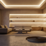
The light exit aperture (LEA) edges: The two lips that define the opening where light comes out. Their flatness, parallelism, and edge sharpness define the crispness of the cut-off line in wall-wash applications. A warp or twist here is immediately visible. Flatness tolerance should be <0.1mm per 100mm length.
Tolerance classes and what they mean for light
This is where we get into the meat of standards. Most references ISO 2768, which covers general tolerances. But there’s a massive gap between the classes.
ISO 2768-mK vs. commercial grade
Many suppliers claim ISO tolerances, but ther are more value to considerate:
| Tolerance class (ISO 2768) | Typical range for a 10mm dimension | Cost & process implication | Optical suitability | Common industry mislabeling |
|---|---|---|---|---|
| f (fine) | ±0.05mm to ±0.1mm | High. Requires precision dies, strict thermal control, frequent measurement, low extrusion speed. High scrap rate. | Excellent. Suitable for high-end architectural, museum, medical. Necessary for micro-optics. | Rarely claimed, often genuine if stated. |
| m (medium) | ±0.1mm to ±0.2mm | Moderate. Standard for quality mechanical parts. Requires good process control. | Good. Suitable for most commercial linear lighting where seamless visual continuity is required. | Often what quality-focused manufacturers like Lightingline.eu use for critical zones. |
| c (coarse) | ±0.2mm to ±0.5mm | Low. “Commercial grade.” High extrusion speed, less die maintenance, higher variance accepted. | Poor. May be acceptable for indirect coves where the source is not visible, but risk of inconsistent gaps. | Often sold as “standard” or “medium” tolerance by low-cost suppliers. |
| v (very coarse) | ±0.5mm to ±1.0mm+ | Very Low. For structural, non-precision work. | Unacceptable. Will cause visible misalignment, optical flaws, and installation headaches. | Should never be used for lighting profiles, but sometimes is for the cheapest products. |
The deception of typical tolerances
A huge problem is quoting “typical” vs. “guaranteed” tolerances. “Our profiles are typically within ±0.15mm” means nothing. What is the process capability index (Cpk)? A Cpk of 1.33 (industry standard for capable processes) means the process spread is 75% of the tolerance window. So if your “typical” is ±0.15mm, your guaranteed tolerance to achieve Cpk≥1.33 should be about ±0.2mm. Ask your supplier for their Cpk data on critical dimensions. I bet 99% can’t provide it. We chart ours for key profiles daily.
Case study – A 100-meter run
Now we would take an example. You’re designing a continuous run of profile for a corporate hallway, 100 meters long, using 5-meter sections butted together. You’re using a 30° micro-prismatic optic for a clean wall wash.
Scenario A (precision supplier): profile optical cavity width tolerance: ±0.1mm (Cpk≥1.33). LED strip placement variance: ±0.05mm. Total lateral LED chip positional uncertainty per section: ≤0.15mm.
Scenario B (standard supplier): profile optical cavity width tolerance: ±0.3mm (poorly controlled). LED strip placement variance: ±0.2mm (because of the loose fit). Total lateral LED chip positional uncertainty: ≤0.5mm.
Now, over 100 meters, you have 20 joints. In scenario A, the worst-case chip position shift from one 5m section to the next is 0.3mm (0.15mm max on one side, 0.15mm min on the other). At a viewing distance of 3 meters, a 0.3mm physical shift creates an angular shift of ~0.006 degrees. Absolutely invisible to the human eye. The line is seamless.
In Scenario B, the worst-case shift is 1.0mm. That creates an angular shift of ~0.02 degrees. Still small? Yes, but the bigger issue is the beam pattern consistency. A 0.5mm lateral shift of the LED relative to the micro-prisms can change the beam intensity distribution by 5-10%. This variance, repeated randomly every 5 meters, creates a perceptible “pulse” or “breathing” in the light along the wall. It’s subtle, but flawed, and it’s possible see tis imperfection.
Material & process
Tolerances aren’t just about the number on the drawing. They depend entirely on the material stability and the extrusion process.
Material: alloy 6063-T5 is the standard for a reason. It has excellent extrudability, good thermal conductivity, and, crucially, it can be held to tight tolerances with minimal post-extrusion distortion. Using cheaper, less controllable alloys like 6060 or off-spec feedstock increases variance. The “T5” temper (solution heat-treated and artificially aged) ensures dimensional stability after cooling. Skipping proper aging to save time leads to profiles that creep and warp over time.
The process: temperature consistency of the billet and container is paramount. Speed must be balanced. Pushing too fast causes heat build-up and larger post-extrusion shrinkage, making dimensions unpredictable. Our lines run slower for critical profiles.
Measurement & QC
You can’t control what you don’t measure. And you can’t measure a 5-meter profile with a caliper every 100mm and call it QC.
Our protocol is:
- first-article inspection (FAI): using a coordinate measuring machine (CMM) with a 0.01mm resolution, we measure every critical dimension on 3 samples from the first 20 meters. This creates a baseline.
- statistical process control (SPC): during the run, we pull a sample every 500kg of extrusion. Key dimensions (cavity width, depth, LEA width) are measured with laser micrometers for speed and accuracy. Data is logged in real-time on control charts.
- full-length flatness & twist check: every piece is rolled on a granite table. Maximum allowable bow is 1mm per meter, 3mm total over 5m. Twist is checked with dial indicators. Any piece outside spec is re-stretched or scrapped.
- Visual/optical check: this is the ultimate test. We mount a reference LED strip and a diffuser/optic onto a sample from each batch, power it up, and project it onto a calibrated screen 2 meters away. We look for intensity variations, color shifts at the edges, and beam angle consistency. A human eye is still the best sensor for perceiving flaws that numbers might miss.
This level of QC adds cost. It’s why our series is more expensive than a generic import. But it’s the cost of guaranteed optical performance.
System integration – The union of profile, optic, and strip
The profile is just one part of the system. Its tolerances must be matched to the other components.
The LED strip: a standard 10mm wide FPC strip has its own tolerance, usually around ±0.2mm. So if you put a 10.0mm ±0.2mm strip into a 10.0mm ±0.2mm cavity, your system clearance can be anywhere from -0.4mm (interference) to +0.4mm (loose). That’s a 0.8mm total range! This is why we often design our profiles with a nominal cavity of 10.2mm for a “10mm” strip, but control the tolerance tightly at ±0.1mm. This guarantees a minimum clearance of 0.0mm (tight fit) and a maximum of 0.4mm, which is manageable with good tape. It’s a system design choice.
The optic: injection-molded PMMA or PC optics also have shrinkage tolerances. A good optic supplier will work with the profile manufacturer to match the snap-fit dimensions. We provide our tolerance datasheets to our approved optic partners so they can design for a perfect interface.
| Component | Critical dimension | Nominal (mm) | Tolerance (mm) | Contribution to system variance |
|---|---|---|---|---|
| LED strip (FPC) | Width | 10.0 | ±0.15 | Medium |
| Lightingline.eu profile | Cavity width (designed for strip) | 10.2 | ±0.1 | Low (tightly controlled) |
| PMMA micro-prismatic optic | Retention clip width | 9.8 | ±0.1 | Low |
| SYSTEM RESULT | LED chip lateral position | — | ±0.25 (calculated) | Excellent (predictable & tight) |
Practical guide
With the checklist below it’s possible step by step have an easy controll of your profile.
- [] Material: alloy 6063-T5, mill certificate to be provided.
- [] General tolerances: To ISO 2768-m, unless otherwise specified.
- [] Critical tolerances (to be called out on drawing):
- LED cavity width: _____ mm ±0.15mm max.
- LED cavity depth: _____ mm ±0.1mm max.
- Light exit aperture width: _____ mm ±0.15mm max.
- Flatness of light exit surface: < 0.2mm/100mm.
- Overall bow: < 1mm per meter, < 3mm total in 5m.
- Overall twist: < 1° per meter.
- [] Quality documentation: first-article inspection report and statistical process control data (Cpk >1.33 for critical dimensions) required before full batch shipment.
- [] Surface finish: anodizing thickness _____ microns. To be even and free from streaks that could cause visible brightness variation.
If a supplier balks at these requests, or says “our standard is good enough,” thank them and move on. They are not a partner for a precision lighting project.
The future – Precision extrusion with µ-Optics and UHP LEDs
The trend is clear: LEDs are getting smaller, brighter, and more demanding. Mini-LEDs and even Micro-LEDs on flexible substrates are coming. These have chip placements tolerances measured in microns (µm). The supporting profile must evolve accordingly.
So means that in the future we could see:
- co-extrusion: combining aluminum for heat sinking with a precisely extruded polymer optical element in a single pass. This eliminates the tolerance stack-up between metal and plastic, locking the optical centerline permanently;
- post-extrusion machining: for ultra-high-end projects, we extrude a “near-net” shape and then CNC mill the critical optical surfaces (like the light exit aperture edges) to a tolerance of ±0.02mm. It’s expensive but creates a perfect reference surface.
- in-Line optical scanning: implementing 100% inspection of critical dimensions with laser scanners, feeding data back in real-time to adjust the press, moving from SPC to fully adaptive process control.
The demand for precision optical alignment will only increase. The extrusion profile will cease to be a commodity and will be recognized as the foundational optical component it truly is.
Extrusion tolerance: the quality of the light depends initially from the profile
In linear LED, the quality of the light is direct function of the precision of the geometry that houses and shapes it for this reason:
- extrusion tolerances are the #1 overlooked spec in linear lighting projects and the most common root cause of visual inconsistency;
- a blanket “±0.3mm” tolerance is unacceptable acceptable only for non-optical, structural parts of a lighting profile. Critical optical zones need ±0.1mm or better;
- tolerance stack-up is a real, calculable enemy. You must consider the interaction between the strip, profile, and optic as a system;
- quality costs money. Precision dies, controlled processes, and rigorous QC (CMM, SPC, light-box tests) add expense but are the only way to guarantee performance. This is the core of the Lightingline.eu philosophy;
- specify, don’t assume. Put tolerance requirements in your drawings and RFQs. Demand data from your supplier. Your reputation as a designer, specifier, or installer depends on the final visual result.
The pursuit of the perfect line of light is connected at increments of hundredths of a millimeter: just enough to make the difference.
References
- ISO 2768-1:1989, “General tolerances — Part 1: tolerances for linear and angular dimensions without individual tolerance indications.”
- Aluminum Extruders Council (AEC), “Design manual for aluminum extrusions.”
- ASTM B221, “Standard specification for aluminum and aluminum-alloy extruded bars, rods, wire, profiles, and tubes.”
- CIE 194:2011, “LED lighting for visual arts & museum applications” (highlights need for uniformity).