Backlighting, the deliberate placement of a light source behind a translucent or diffusing surface, is the defining technique in professional signage manufacture, retail display engineering, and architectural lighting design. Whether you are fabricating a large-format outdoor light box, a set of illuminated channel letters for a retail facade, or a slim backlit panel for an exhibition stand, the quality of your backlighting determines everything: the visual impact, the energy efficiency, the longevity of the installation, and ultimately the perception of the brand it represents. This guide is the most comprehensive resource currently available for sign-makers, display fabricators, interior designers, electrical engineers, and content creators who want to master led backlighting at a professional level: covering not just the theory and the physics, but the exact products, tools, cutting techniques, connection methods, and driver configurations that separate a mediocre result from a flawless one.
In questo articolo…
- What is backlighting? Definition, history and modern applications
- The physics of backlighting: how light behaves inside an enclosure
- Led technology for backlighting: strips, COB, modules and rigid bars
- Luminance uniformity: eliminating hot spots and the dotted effect
- Aluminum profiles for signage backlighting: the LightingLine architecture
- Cutting and connecting LED strips: tools, techniques and common mistakes
- Driver configuration: constant voltage, constant current and surge protection
- Backlighting channel letters: step-by-step professional method
- Backlighting light boxes: depth, diffusion and layout strategy
- RGB and dynamic backlighting: smart control systems for animated signage
- LED backlighting, health and wellbeing: flicker, blue light and circadian rhythm
- Backlighting for retail, photography and content creation
- The LightingLine architecture of uniformity
- Market data, industry statistics and trends
- Frequently asked questions
- Building better backlighting
What is backlighting? Definition, history and modern applications
Before examining the technical details of LED backlighting systems for professional signage, it is essential to understand what backlighting actually means, where the concept originates, and how its definition has evolved as technology has advanced. Understanding the fundamentals of backlight lighting helps both seasoned engineers and newcomers make better decisions at every stage of a project, from concept to installation. The term appears across disciplines (photography, electronics, film, architecture) and while its surface meaning is consistent, the technical requirements differ substantially between contexts, making a rigorous foundational understanding indispensable before any practical work begins.
The meaning and definition of backlighting
In its most precise technical sense, backlighting refers to the illumination technique in which a light source is positioned behind the primary subject or display surface, transmitting light forward through that surface to create a uniformly glowing effect. The meaning of backlighting is therefore both literal and functional: literal because the light source is physically placed at the back, functional because the purpose is to create a controlled, perceptually uniform luminous surface visible from the front.
The concept of backlight lighting predates modern electronics by centuries. Stained glass windows in Gothic cathedrals relied on the same fundamental principle: daylight placed behind the coloured glass surface creates luminous, vibrant colour visible from the front interior. The purpose of backlighting in that ancient context was symbolic and spiritual while in modern signage, retail, and display applications, the purpose is functional and commercial, but the underlying optical mechanism is identical. The first industrial application of controlled backlighting arrived with the introduction of lightboxes for X-ray film viewing in the early twentieth century, where fluorescent tubes were mounted behind a frosted diffuser screen, a configuration that remains recognisable in today’s LED light bar backlighting systems. The definition of backlighting has therefore remained conceptually stable for over a century, even as the light sources themselves have changed radically.
What backlighting is used for today spans at least six distinct industrial and creative sectors:
- signage and display fabrication: illuminated channel letters, light boxes, tension fabric displays, and blade signs;
- consumer electronics: LCD screens rely on a backlighting screen layer (edge-lit or full-array LED backlighting) to make images visible;
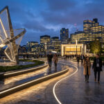
- architectural and interior design: backlit panels, ceilings, floors, feature walls, and furniture;
- photography and filmmaking: backlighting as a creative technique to rim-light subjects or create silhouettes and mood;
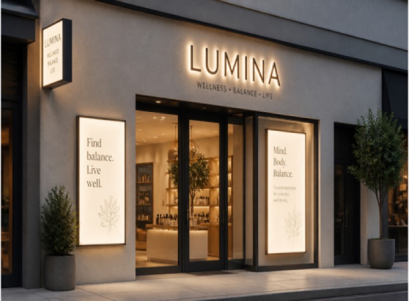
- retail and point-of-sale: backlit product displays, menu boards, window graphics, and shelf edge strips;
- content creation and streaming — background lights and rgb backlight setups for video production and social media.
Each context has its own technical requirements, but the LED backlighting kit products developed for professional signage (with their emphasis on luminance uniformity, thermal management, and robust driver configurations) represent the highest standard of the technology and provide the foundation for understanding any backlighting application. What backlighting does, fundamentally, is transform a surface from a passive reflector into an active luminous element, an object that appears to generate its own light rather than merely bouncing light from external sources. This transformation creates visual impact that is commercially and aesthetically extraordinary.
A brief history of backlight technology
The history of the backlight led revolution is remarkably compressed relative to the depth of its impact. For most of the twentieth century, backlighting meant fluorescent technology. Cold Cathode Fluorescent Lamps (CCFLs) were the dominant light source for LCD backlighting in computer monitors, televisions, and portable devices from the 1980s through the mid-2000s. In signage, hot-cathode fluorescent tubes (the familiar T5 and T8 lamps installed in light boxes, menu boards, and poster cases worldwide) illuminated commercial spaces and public environments with reasonable efficiency and adequate colour rendering for the expectations of the time.
The first commercially viable white LEDs appeared in the late 1990s following the Nobel Prize-winning development of the blue LED, but early efficiency was too low and colour rendering too poor for demanding backlighting applications. The breakthrough arrived between 2005 and 2010, when LED efficacy crossed the 80 lm/W threshold and colour rendering index (CRI) values began exceeding 80 Ra consistently. By 2012, LED backlit television displays had captured the majority of the flat-panel market, and by 2015, LED strips had become the default choice for new commercial sign installations across Europe and North America. The fluorescent lamp, an invention of the early twentieth century, was displaced in less than a decade by a superior technology that offered longer life, lower energy consumption, no mercury content, instant starting in cold weather, and the ability to be dimmed smoothly to any level.
Today, the evolution continues at an accelerating pace. COB (Chip on Board) technology is redefining what is possible in shallow-depth signage. Full-array LED backlighting with local dimming is transforming the contrast performance of digital signage displays. Smart rgb backlight systems with per-pixel SPI control are enabling animated, attention-capturing sign effects that were commercially impractical even five years ago. The economic and environmental case for LED over all alternatives is now definitive and essentially uncontested: modern LED strips achieve 140–180 lm/W efficacy, operate for 50,000–100,000 hours, contain no mercury or other hazardous substances, and can be dimmed to any level between 0% and 100% without affecting colour temperature, colour rendering, or operational lifespan.
What does backlighting do? Purpose, function and effect
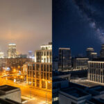
The purpose of backlighting varies by application context, but a consistent set of functions applies universally. Backlighting enables visibility in environments where ambient light is insufficient to make a surface readable or visually compelling on its own. It creates the perception of internal luminosity, the illuminated surface appears to generate its own light rather than reflecting external illumination. In signage, this dramatically increases legibility and visual impact over long distances and in adverse lighting conditions, including direct sunlight competition, heavy rain and reduced visibility, and the fundamental challenge of night-time environments where unlit signs become invisible.
What the backlighting effect does to the viewer is both perceptual and psychological. Perceptually, a backlit surface has a fundamentally different appearance from a front-lit surface of identical graphic content: the colours appear more saturated, the contrast between light and dark elements is higher, and the overall luminance is more uniform because it is generated internally rather than being dependent on the angle and intensity of external light sources. Psychologically, a glowing surface commands attention in a way that a passive reflective surface cannot, it is perceived as more important, more premium, and more worthy of close attention. Retail studies consistently demonstrate that backlit displays generate significantly higher dwell time and purchase intent than their non-illuminated equivalents, with some studies reporting customer engagement uplifts of 25–40% for backlit point-of-sale material compared to front-lit or unlit alternatives.
In photography and filmmaking, the backlighting effect creates the iconic rim-light halo around a subject that has defined the visual language of countless commercial and cinematic images. The mood backlighting creates is typically dramatic, ethereal, aspirational, or mystical, qualities that explain its enduring popularity in fashion photography, luxury brand advertising, spiritual and religious imagery, and cinematic storytelling. Understanding how LED backlighting creates this mood at the technical level (the physics of light transmission, diffusion, and the rendering properties of specific light sources) is the key to controlling and reproducing it professionally and reliably.
The backlighting effect in signage is measured primarily in terms of luminance (cd/m²), the brightness perceived by the human eye from a specific viewing angle, and uniformity ratio which is the ratio of minimum to maximum luminance across the illuminated surface. A uniformity ratio of 0.75 or higher is considered acceptable for most signage applications; premium installations require 0.85 or above. Achieving these metrics consistently and economically is the central technical challenge that this guide addresses in depth.
The physics of backlighting: how light behaves inside an enclosure
To design a backlighting system that delivers perfect luminance uniformity, whether for a large-format led light bar backlighting installation or a compact set of channel letters, it is necessary to understand the basic optical and thermal physics governing how light behaves once it is emitted from an LED source inside a sealed enclosure. This section provides a clear, practical explanation of the key physical principles, calibrated to the knowledge level of a professional sign-maker or lighting designer who needs actionable understanding rather than academic derivation. Backlighting works through a set of well-understood optical phenomena that can be engineered predictably once their governing principles are internalised.
Light emission, beam angle and the propagation geometry
Every LED (whether in a strip, a module, or a COB package) emits light within a defined beam angle, typically expressed in degrees and measured as the full angle at which the intensity falls to 50% of its peak value (FWHM, Full Width at Half Maximum). Standard SMD LEDs on commercial strips have a beam angle of 120°, meaning light is spread across a wide hemisphere in front of the chip. When this light source is placed inside a shallow enclosure such as a channel letter, the geometry of light propagation determines whether the illuminated face will appear uniform or will show distinct “dots” and “hot spots.”
The critical geometric relationship is between the LED pitch (the centre-to-centre distance between individual LED chips), the beam angle, and the source-to-diffuser distance. As light travels away from the LED source, the beam cone expands in diameter. When the beam cones from adjacent LEDs overlap (creating a zone of consistent, blended illuminance) the surface behind which they merge appears uniformly lit. When they do not overlap before reaching the diffuser, the diffuser surface shows regions of higher illuminance (directly in front of each LED) and lower illuminance (between LEDs), creating the visible dotted pattern that is the primary quality failure in channel letter and shallow light box backlighting.
The inverse square law of illuminance governs the quantitative relationship: illuminance on a surface decreases in proportion to the square of the distance from the source. A surface placed 20 mm from an LED receives four times more light than a surface placed 40 mm away from the same source. This means that in a very shallow enclosure (e.g., 10 mm depth), the illuminance at the surface is dominated by the direct flux from the nearest LED, with very little contribution from adjacent LEDs, creating extreme non-uniformity. In a deep enclosure (e.g., 80 mm), the contribution from a given LED is spread over a much larger area at the surface, and the contributions from all LEDs in the vicinity blend to produce a more uniform illuminance distribution. This is the fundamental physical reason why depth is the most powerful lever for achieving luminance uniformity in backlighting, and why the choice between shallow and deep enclosures is the primary design trade-off in every signage backlighting project.
Diffusion: the optical role of the diffuser
A diffuser, whether an opal acrylic face, a frosted polycarbonate sheet, or a satin-finish profile cover, performs two optical functions simultaneously. First, it scatters light by breaking the coherent directionality of the incident beam, redistributing luminous intensity over a wider range of emission angles. Second, it absorbs a proportion of the incident flux, which reduces the overall brightness of the system but smooths out the luminance variation between the areas above and between LED chips. The combined result is a surface that appears more uniform than the light field incident upon it, but at the cost of some luminous efficiency.
The trade-off between uniformity and efficiency is one of the central design decisions in any backlighting system, and it cannot be optimised in isolation, it must be considered together with the source-to-diffuser distance and the LED density. An opaque white diffuser (FM or FS cover type) may absorb 44–48% of the incident flux but deliver uniformity ratios of 0.88–0.92 at appropriate depths. A lightly frosted cover (FK type) transmits 74% of the incident flux but produces uniformity ratios below 0.50 unless the source-to-diffuser distance is large. A transparent cover (FT type) transmits 92% or more but provides no diffusion benefit whatsoever. For professional signage applications where uniform appearance is the paramount quality criterion, high-opacity diffusers are the correct choice in almost all circumstances, even at the cost of luminous efficiency, because the additional LED power required to compensate for diffuser absorption is economically trivial compared to the value of the visual quality improvement.
Reflectance: the interior surface as a system component
The interior surfaces of a channel letter or light box, the back panel and the return walls, are as important to the final backlighting quality as the LED source itself, yet they are the most consistently neglected element in field installations. Surfaces painted or lined with high-reflectance white (reflectance coefficient R ≥ 0.85) multiply the effective flux available to the diffuser by redirecting light that would otherwise be absorbed or escape in non-useful directions back toward the face. Commercial signage interiors are typically finished with a white powder coat or lined with highly reflective white PVC or aluminium sheeting with reflectance values of 0.90–0.95.
The quantitative impact of interior reflectance is striking: the difference between an untreated bare aluminium interior (R ≈ 0.60) and a well-prepared white-painted interior (R ≈ 0.90) can increase the apparent luminance of the sign face by 40–60% for the same LED input power — a substantial gain achievable at negligible cost. For letters painted with matt black interior (R ≈ 0.05) — an error sometimes made by fabricators who confuse interior and exterior surface treatment requirements — the luminance penalty can exceed 70%, meaning that a correctly white-lined version of the same letter with the same LED source would appear three times brighter. This makes interior surface treatment one of the highest-return optimisations available in any signage backlighting project.
Thermal management: why heat is the primary long-term failure mode
LED efficacy and operational lifespan are critically dependent on junction temperature, the temperature at the semiconductor junction inside each LED chip. The relationship between junction temperature and lifespan is exponential: for every 10°C rise in junction temperature above the manufacturer’s rated value, the expected lifespan of the LED is approximately halved according to the Arrhenius thermal degradation model. In an enclosed channel letter or sealed light box without adequate thermal management, junction temperatures can easily rise 30–50°C above ambient, reducing a theoretically rated 50,000-hour LED lifespan to fewer than 10,000–15,000 hours in practice, and substantially reducing the luminous output well before the LED reaches its nominal end-of-life point.
Aluminium LED profiles serve the primary function of a heat sink, drawing thermal energy away from the LED strip’s PCB through conductive contact and dissipating it through the profile’s mass and surface area into the surrounding environment. The thermal resistance (θ_sa, expressed in °C/W) of the profile must be matched to the power dissipation of the LED strip to maintain acceptable junction temperatures. A high-power strip running at 20 W/m in an enclosed channel letter requires a substantially more massive profile with greater aluminium section than a 5 W/m decorative strip. Selecting the correct profile cross-section for the power level of the chosen strip is not optional, it is the single most important factor in determining the long-term reliability and maintained output of the backlighting installation.
| LED strip power (W/m) | Recommended profile type | Min. aluminium section (cm²) | Expected lifespan (25°C ambient) |
|---|---|---|---|
| Up to 8 W/m | Slim surface or recessed profile | 3–5 cm² | 50,000+ hours |
| 8–15 W/m | Standard surface or corner profile | 6–10 cm² | 40,000–50,000 hours |
| 15–25 W/m | Wide-body or deep signage profile | 10–16 cm² | 30,000–40,000 hours |
| 25+ W/m | Heavy-duty extrusion with fins | 18+ cm² | 25,000–35,000 hours |
The critical distance formula: a practical calculation tool
For any given LED strip and enclosure depth, the concept of critical distance (also called mixing distance or homogenisation distance) provides a practical calculation tool. The critical distance is the minimum source-to-diffuser distance at which the light from adjacent LEDs overlaps sufficiently to produce a visually uniform illuminated surface. The empirically derived formula most widely used in professional signage engineering is:
Critical distance (mm) ≈ LED pitch (mm) × 0.6
For example, a standard 60 LEDs/m strip has a chip pitch of 16.7 mm, giving a critical distance of approximately 10 mm, manageable even in quite shallow letters. A 30 LEDs/m strip has a pitch of 33.3 mm, giving a critical distance of approximately 20 mm, feasible for most channel letter depths but marginal for very shallow signs. A high-quality diffuser (FM/FS type) effectively reduces the perceived critical distance by approximately 30–40% compared to no diffuser, so the same strip can achieve acceptable uniformity at a shallower depth when a high-opacity diffuser is used. COB strips effectively reduce the LED pitch to near-zero, making the critical distance formula irrelevant (uniform illumination is achievable at any practical source-to-diffuser distance) including the ultra-shallow geometries of 5–10 mm that are impossible to achieve acceptably with any non-COB technology.
LED technology for backlighting: strips, COB, modules and rigid bars
The led backlighting market offers a wide and rapidly evolving variety of light source configurations, each with specific strengths and limitations for professional signage applications. Understanding the technical differences between conventional SMD strip lights, COB continuous-line technology, led module lights, and rigid led light bar backlighting products is essential for making correct product selections across the full range of project types and ensuring that every installation delivers the luminance uniformity and longevity that professional-grade signage demands.
Standard SMD LED strips: the established workhorse
Standard SMD (Surface Mount Device) LED strips are the most widely deployed format in backlighting applications worldwide and have been the industry standard for commercial signage for the past decade. They consist of a flexible PCB substrate onto which individual LED packages are soldered at regular intervals, typically 16.7 mm (60 LEDs/m), 8.3 mm (120 LEDs/m), or 33.3 mm (30 LEDs/m), with current-limiting resistors integrated into each group of three or four LEDs to regulate operating current independent of supply voltage variations. Each individual LED is a discrete emitter with a defined flux output, beam angle, colour temperature, and CRI specification.
The most common type of backlighting in commercial signage over the past decade has been the SMD 2835 or SMD 5630 strip in cool white (5000–6500K) or neutral white (4000–4500K), operating at 24V DC (preferred over 12V for longer run lengths and lower cable losses). These strips balance cost, availability, luminous efficacy (100–140 lm/W for current commercial grade), and ease of installation in a way that no competing technology has fully displaced for medium-depth light boxes and standard signage applications. A 60 LEDs/m SMD 2835 strip operating at 10–14 W/m and producing 1200–1800 lm/m represents the value sweet-spot of the signage LED strip market and will continue to do so for the near future. For light boxes with depths of 50 mm or more and any sign where a clear or lightly frosted face provides additional diffusion, standard SMD strips on appropriate aluminium profiles remain an entirely professional choice.
However, for shallow channel letters and applications requiring dot-free uniformity at very short source-to-face distances, standard SMD strips are progressively being replaced by COB technology as the professional standard. The quality gap between COB and standard SMD at depths below 25 mm is significant enough to be visible to untrained observers, and in a premium commercial sign installation, any visible quality deficiency is unacceptable. Knowing when to specify COB over SMD is one of the most practically important skills in professional signage lighting design.
COB LED strips: the professional standard for shallow channel letters
COB (Chip on Board) LED strip technology represents the most significant advance in flexible strip lighting since the original commercialisation of SMD strip technology. Instead of mounting individual LED packages at discrete intervals, COB technology places hundreds or thousands of tiny bare LED chips directly onto the PCB substrate (at densities of 300 to 600+ chips per metre) and covers them with a single continuous phosphor-in-silicone (PiS) coating that converts the blue chip emission into broad-spectrum white light. The result is a strip that emits light from its entire length as a continuous, seamless line — with no individual points of brightness, no visible pitch pattern, no dots, and no directionality variations along the strip axis.
For backlighting channel letters and shallow light boxes, the implications of COB technology are transformative. The critical distance for a COB strip is effectively zero: even at a source-to-diffuser distance of 5–8 mm, the light appears perfectly uniform when an FM or FS diffuser is used, because there are no discrete emission points to create non-uniformity, only a continuous line source. This makes COB the enabling technology for the modern generation of ultra-thin illuminated signs, where total letter depth may be as little as 10–15 mm, a geometry that would have been considered technically impossible for backlit signage even ten years ago. The adoption of COB technology in professional signage has directly enabled the visual trend toward ultra-slim, architecturally refined channel letters that increasingly characterise premium commercial signage in retail, hospitality, and corporate environments.
The F52-300-320OR2 series and FA2-400-480OR2 series deliver a combination of continuous-line emission, high efficacy (140–160 lm/W), excellent colour rendering (CRI ≥ 90), and a consistent 24V operating voltage that satisfies the most demanding professional signage specifications. At these efficacy levels, the ratio of heat generated per unit of luminous output is substantially lower than for lower-efficacy alternatives, which is critical for enclosed channel letters where there is minimal convective air circulation to remove heat. The high-CRI specification ensures that coloured acrylic faces and printed graphics are rendered with accurate, saturated colour that matches the design intent.
COB vs SMD: technical comparison for professional backlighting
| Parameter | Standard SMD strip | COB strip |
|---|---|---|
| Emission character | Discrete point sources at regular intervals | Continuous line source with no visible pitch |
| Minimum useful depth (channel letter) | 20–40 mm (depending on density) | 5–10 mm |
| Luminance uniformity at 10 mm depth | Poor (dots clearly visible) | Excellent |
| Typical efficacy (current commercial) | 100–140 lm/W | 130–165 lm/W |
| CRI availability | 70–95 Ra | 80–98 Ra |
| Minimum cut length | 25–100 mm depending on LEDs/m | 25–50 mm (series dependent) |
| Cost relative to SMD | Baseline (index 100) | 115–135 |
| Best application | Deep light boxes (>50 mm), large format | Channel letters, slim lightboxes, precision work |
| IP rating availability | IP20 through IP68 | IP20 through IP67 |
LED module lights for backlighting
LED module lights are discrete unit sources, typically 30×30 mm to 50×50 mm per unit, containing one or more high-power LED chips on a small PCB with an integrated lens that controls the beam angle and, in many cases, a pre-applied silicone coating for environmental protection. They are connected in parallel strings and designed to be mounted directly to the interior surface of channel letters or light boxes at calculated spacing intervals, typically 50–100 mm between units depending on the enclosure depth and the target uniformity.
The primary advantage of LED modules for backlighting over strip formats is their ability to project a precisely defined beam pattern across the interior of a sign. Modules with wide beam angles (160°) maximise the illuminated area per unit in shallow letters, modules with medium beam angles (90–120°) are preferred in deeper boxes where more directed light increases the flux incident on the diffuser face. The per-module approach also simplifies the calculation of total flux and power consumption compared to continuous strips, since each module has a precisely specified lumen output and power consumption. IP65-rated silicone-dome modules are specifically designed for channel letters where condensation or occasional moisture ingress is possible — the silicon dome simultaneously provides the lens function and the moisture protection in a single integrated component.
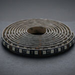
Rigid LED light bars for backlighting
LED light bar backlighting uses rigid aluminium extrusions with integrated LED strips and pre-fitted diffuser covers as self-contained, ready-to-install backlight modules. These products are particularly valuable for retrofit installations in large-format light boxes where the original fluorescent tubes are being replaced with LED, since their tube-like form factor and standard lengths (300 mm, 600 mm, 1200 mm) allow them to be installed in existing fluorescent mounting positions without structural modification of the sign cabinet. Rigid bars deliver the efficiency and longevity advantages of LED technology within the mechanical envelope of the fluorescent tube, making them the most cost-effective solution for simple retrofit projects where the cabinet geometry is fixed and unchanged.
For large outdoor light boxes (billboard faces, bus shelter illumination, and large menu boards) LED rigid bars in a parallel array provide consistent, easily calculated backlighting at scale. The bar-based approach simplifies maintenance since individual bars can be replaced independently if one section fails, without disturbing the rest of the system. The ability to replace individual bars also means that the system can be upgraded piecemeal as higher-efficacy products become available, rather than requiring a complete refit.
RGB and colour-changing LED strips for dynamic backlighting
RGB backlight and RGBW strip configurations bring dynamic colour capability to professional signage backlighting. By independently controlling the red, green, and blue (and optionally white) channels via a compatible PWM controller or SPI decoder, RGB systems can produce any colour across a wide gamut and enable the creation of animated, schedule-responsive, or even interactive signs that adapt their visual character to the context, season, or event. The integration of pixel SPI-addressable LED strips (where each LED or small group of LEDs can be individually addressed by the control system) extends dynamic backlighting to the level of full-motion animation within the sign body, where light appears to flow, chase, or pulse through the letter forms or panel as a deliberate visual effect.
For professionals considering rgb backlight for commercial signage, the key technical considerations are: the colour gamut achievable (defined by the specific chip chemistry and the phosphor treatment of each R, G, and B channel), the minimum colour mixing distance required (RGB strips need greater source-to-diffuser distance than white strips to allow the three colour channels to blend completely, typically 30–50 mm minimum), the control protocol and its compatibility with the client’s existing control infrastructure, and the precision with which colour matching can be maintained over time as the LED chips gradually age differentially.
Luminance uniformity: eliminating hot spots and the dotted effect
Luminance uniformity is the single most critical quality metric in professional backlighting for signage, and it is the parameter that most directly determines whether a finished sign looks professionally excellent or disappointingly mediocre. A sign with poor uniformity (visible bright spots directly above each LED, dark edges, or the characteristic dotted appearance where individual LED chips show through the face) communicates poor quality to every observer regardless of how well-executed the graphic design or branding may be. Achieving professional-grade uniformity across the full range of sign types and depths requires a systematic understanding of the four interacting variables: source technology, LED density, enclosure geometry, and diffuser specification. This section provides that understanding in the form of practical principles and reference data that can be applied directly in project design.
Defining and measuring the uniformity ratio
Luminance uniformity is quantified as the ratio of minimum luminance (L_min) to maximum luminance (L_max) measured at a representative set of points across the illuminated face of the sign, expressed as a dimensionless value between 0 and 1:
Uniformity Ratio (U) = L_min / L_max
A value of 1.0 represents perfect uniformity — every point on the surface at precisely the same brightness, which is a theoretical ideal never achieved in practice. A value of 0.0 represents infinite non-uniformity. Professional applications have specific target ranges:
| Application type | Min. acceptable U | Target professional U |
|---|---|---|
| Backlit menu boards (deep box, >60 mm) | 0.70 | 0.85+ |
| Standard channel letters (depth 50–80 mm) | 0.65 | 0.80+ |
| Shallow channel letters (depth 20–50 mm) | 0.60 | 0.75+ |
| Ultra-shallow letters (depth <20 mm, COB) | 0.70 | 0.82+ |
| Premium retail light boxes | 0.80 | 0.90+ |
| Exhibition display panels | 0.75 | 0.88+ |
| Architectural backlit panels (interior) | 0.85 | 0.92+ |
The five proven strategies for maximum uniformity
Strategy 1: increase source-to-diffuser distance
Increasing the depth of the enclosure is the most physically direct approach to improving uniformity. Deeper enclosures allow individual beam patterns from each LED to spread and overlap more completely before reaching the diffuser, smoothing out the luminance gradient between LED positions and inter-LED gaps. For standard 60 LEDs/m SMD strips, a depth of at least 40–50 mm is needed for acceptable uniformity; for 30 LEDs/m strips, a minimum of 60–80 mm is recommended. The limitation is that many sign types — particularly slim channel letters and thin-format display products — cannot be made arbitrarily deep without compromising the design intent or the structural constraints of the installation.
Strategy 2: increase LED density
Using a higher-density strip (more LEDs per metre, smaller pitch) reduces the distance between adjacent light sources, which reduces the critical mixing distance proportionally and allows acceptable uniformity at shallower depths. Doubling the strip density from 30 to 60 LEDs/m halves the critical distance; doubling again from 60 to 120 LEDs/m halves it once more. In practical terms, specifying a 120 LEDs/m strip instead of a 30 LEDs/m strip allows the same uniformity to be achieved at one quarter of the depth, a significant design freedom in shallow signage. The trade-off is cost (higher-density strips cost more per metre) and thermal load (more LEDs per unit length means more watts per unit length for the same system voltage), both of which are manageable for most professional applications.
Strategy 3: switch to COB technology
COB LED strips eliminate the pitch problem entirely by providing a continuously distributed light source with no discrete gaps. This is the definitive solution for any channel letter or shallow display where uniformity requirements cannot be met by density increases alone, and it is the professional standard for all new-construction shallow channel letters in the premium signage market. The cost premium over standard SMD strips (typically 15–35%) is justified by the quality of the result, the elimination of rework and client complaints related to visible dots, and the competitive positioning of the fabricator as a provider of premium-quality backlighting.
Strategy 4: optimise diffuser specification
Selecting a higher-opacity diffuser increases the light scattering coefficient and improves uniformity by blending non-uniform incident illuminance into a more even surface luminance. For signage backlighting, opaque white (FM) or satin white (FS) profile covers are the correct default for virtually all professional applications. Lightly frosted (FK) covers are appropriate only for deep light boxes where efficiency is critical and depth alone provides adequate uniformity. The efficiency penalty of FM/FS diffusers — 44–48% light absorption — must be compensated by specifying a higher-output LED strip, but this is a straightforward calculation and the quality benefit is significant.
Strategy 5: maximise interior surface reflectance
Finishing the interior of channel letters and light boxes to the highest achievable reflectance, using white paint (R ≈ 0.80–0.85), white powder coat (R ≈ 0.85–0.88), or high-reflectance white film (R ≈ 0.92–0.95), redirects escaped light back toward the diffuser face and contributes to luminance smoothing through inter-reflections. This is a low-cost, high-impact intervention that can improve uniformity ratios by 0.05–0.10 in typical configurations at essentially no additional LED cost. It should be standard practice in every channel letter and light box fabrication operation.
Aluminum Profiles for Signage Backlighting: The LightingLine Architecture
Aluminium profiles are the structural backbone of every professional LED backlighting installation for signage. They perform three simultaneous functions (thermal management of the LED source, optical housing to control diffusion geometry, and mechanical protection of the strip and its connections) and the selection of the correct profile type for a given application is one of the most consequential decisions in the entire design process. A correctly chosen profile that is thermally matched to the LED strip’s power density, dimensionally suited to the required diffusion depth, and finished with the appropriate cover type will deliver professional-grade backlighting reliably for a decade or more. An incorrectly chosen profile, regardless of how good the LED strip or driver specification may be, will produce either overheating and premature failure (thermal mismatch), visible non-uniformity (depth mismatch), or excessive light loss (wrong diffuser cover).
Deep housing for superior diffusion: the PR-CL02-07
For large light boxes and deep signage where luminance uniformity is the overriding design priority, the CL02-07 profile (50×75 mm) represents the professional benchmark solution. Its 75 mm internal depth provides the extended diffusion path that allows standard 60 LEDs/m SMD strips to achieve uniformity ratios of 0.85 and above without any additional optical components, making it the simplest and most reliable solution for large-format light boxes where depth is not architecturally constrained.
The large internal cross-section of the CL02-07 provides outstanding thermal performance, with low thermal resistance that supports high-power strips of 20 W/m and above without exceeding recommended junction temperatures even in warm outdoor environments. The 50 mm width accommodates dual-row strip configurations for applications requiring maximum flux output (large-format outdoor advertising panels, roadside directional signs, and full-size illuminated site fascias where luminance must compete with direct sunlight). The substantial aluminium section also provides excellent mechanical stability, ensuring that the profile remains straight and true over long runs without the sagging or bowing that can occur with lighter-section profiles when installed horizontally at spans above 1.5 m.
Ultra-slim solutions
At the opposite extreme of the depth spectrum, the SL13-02 profile at just 5 mm high enables the ultra-slim backlit aesthetics demanded by premium retail interior design, high-end exhibition stands, and modern architectural signage where visual slimness is itself a design value. At 5 mm total height, this profile is thinner than a typical smartphone, making it essentially invisible when flush-mounted on a wall or integrated into a display system, the light appears to emanate from the surface itself rather than from an applied component.
The engineering constraint of this profile must be clearly understood: at 5 mm depth, only COB LED strips or very high-density SMD strips at 120+ LEDs/m can deliver acceptable luminance uniformity. Standard 30 or 60 LED/m strips will produce clearly visible dots regardless of diffuser choice at this depth, because the source-to-diffuser distance is far below the critical mixing distance. The PR-SL13-02 is therefore specifically matched to COB strip technology, and the two should always be selected together as a system. When this combination is correctly applied, the result is a seamlessly glowing surface of extraordinary thinness that represents the state of the art in slim-format LED backlighting and a competitive differentiator for fabricators serving the premium design market.
Trimless integration: the PR-DW series
High-end architectural signage (the kind designed for luxury retail environments, premium hotel lobbies, corporate headquarters, and boutique hospitality venues demands an invisible installation where the light source appears to be an intrinsic part of the architecture rather than an added component. The PR-DW07 has been specifically engineered for this context: its flanges are designed to be plastered, skimmed, or finished over during installation so that only the light-emitting aperture remains visible after the building work is complete. The result is a light source that appears to be built into the wall, ceiling, or architectural element itself, the “invisible” lighting effect that characterises the very best contemporary architectural lighting design.
This “trimless” or “plasterboard integration” approach places demanding requirements on the installation process. The profiles must be positioned with millimetre accuracy before the plasterboard compound or skimming is applied, because post-installation positional adjustment is impossible without substantial remedial work. The LED strip must be installed and all electrical connections made and fully tested before the profile flanges are embedded in the finished surface. A detailed installation drawing with precise dimensional referencing to the building structure, followed by a comprehensive pre-embedding test of all electrical and optical functions, is a non-negotiable prerequisite for a successful trimless backlighting installation using the PR-DW series. The higher skill and planning demands of this approach are reflected in the installation day-rate that premium signage and architectural lighting contractors can legitimately charge for this work.
Diffuser cover selection reference
LightingLine offers each profile family with a standardised range of cover (diffuser) options, identified by suffix codes in the product designation:
| Cover code | Type | Light transmission | Uniformity effect | Best application |
|---|---|---|---|---|
| FM | Frosted Milk (opaque white) | 52–56% | Excellent scattering, hides dots completely | Channel letters, shallow signage |
| FS | Frosted Satin (white) | 52–56% | Excellent scattering | Standard signage, retail display |
| FK | Frosted (near-transparent) | 72–76% | Moderate scattering | Deep light boxes (>60 mm) |
| FT | Transparent (clear) | 90–94% | Minimal scattering, dots visible | Architectural accent, not signage face |
| FC | Coloured tint | Variable | Good scattering (same as FM/FS) | Coloured sign faces |
For professional signage backlighting, FM and FS covers are the correct default in the vast majority of cases. The efficiency penalty of 44–48% light retention relative to an FK cover must be factored into the LED strip specification: the strip must deliver sufficient luminous flux at the source to ensure adequate face luminance after diffuser absorption. At the efficacy levels of LightingLine’s professional COB strips (140–160 lm/W), this compensation is achievable without excessive power consumption or heat generation, making the FM/FS + COB combination the optimum system specification for professional signage backlighting in the vast majority of applications.
Cutting and connecting LED strips: tools, techniques and critical rules
Even the highest-quality led backlighting kit components will produce a poor or unreliable result if the LED strips are cut at the wrong points, connected with incorrect tools, or installed without attention to polarity, contact quality, voltage drop management, and environmental protection. This section provides the definitive professional guide to cutting and connecting LED strips for signage backlighting: covering every strip type in common use, every connection method from soldering to push-in connectors, every common failure mode and its prevention, and the specific techniques required for each of the main strip technologies including COB, RGB, and addressable pixel strips. The goal is to make installation errors impossible rather than merely unlikely.
Essential tools and materials
Before beginning any LED strip installation for professional signage backlighting, the following tools and materials should be assembled, verified, and in good working condition:
- Sharp scissors or dedicated flat-blade LED strip cutters: standard kitchen scissors work adequately for standard SMD strips, but dedicated LED strip cutters with clean, perpendicular blades minimise the risk of delaminating PCB copper traces at the cut. For COB strips, very sharp, fine-bladed scissors are required to cut cleanly through the phosphor layer without fraying.
- Precision steel rule and fine-tip marking pen: for accurately marking cut lines on PCB substrates.
- 10× magnifying glass or loupe: for inspecting cut edges, verifying copper pad integrity, and confirming that no solder bridges have formed between adjacent pads.
- Temperature-controlled soldering iron (300–350°C tip): and fine solder (0.6 mm, 60/40 or lead-free) — for maximum-reliability soldered connections.
- High-quality strip-to-strip and strip-to-wire push-in connectors: for tool-free connections at accessible junction points. Quality is non-negotiable: substandard connectors are the single most common source of intermittent faults in completed LED signage.
- Heat gun (50–80°C) and heat-shrink tubing in appropriate sizes: for weatherproofing connections and providing strain relief.
- Isopropyl alcohol (IPA) and lint-free cloths: for cleaning cut pad surfaces before soldering or connecting.
- Digital multimeter: for polarity verification, voltage drop measurement, continuity testing of connections, and current measurement before final assembly.
- Double-sided thermal tape and/or aluminium mounting clips: for strip-to-profile bonding with supplementary mechanical retention.
The fundamental rule: cut only at marked points
This is the single most important operational rule in LED strip installation, and it must be internalised absolutely: LED strips can only be cut at the designated cut marks printed on the PCB, never between them, never “close to” them, and never at a point selected for dimensional convenience if it does not coincide with a marked cut position. The cut marks, typically indicated by a scissors icon and/or a dashed printed line on the PCB substrate, correspond to the location of the current-dividing resistor groups that separate individual LED supply circuits. Cutting between marked positions severs one or more resistors or trace connections, rendering the affected LED group permanently non-functional and potentially creating a short circuit that damages adjacent components.
The minimum cut length (the length of each individually cuttable segment) varies by strip type and density:
- SMD 2835, 30 LEDs/m: 100 mm (3 LEDs per segment)
- SMD 2835, 60 LEDs/m: 50 mm (3 LEDs per segment)
- SMD 2835, 120 LEDs/m: 25 mm (3 LEDs per segment)
- COB 320 effective LEDs/m: typically 25–50 mm depending on series
- RGB strip, 30 LEDs/m: 100 mm (one group of R+G+B per segment)
- RGBW strip, 60 LEDs/m: 50 mm
- SPI addressable pixel strip: 1 pixel pitch (typically 33 mm for 30 pixels/m)
Cutting technique by strip type
Standard single-colour SMD strips
Mark the cut line at the printed scissors mark using a fine pen. Align scissors or a flat cutter perpendicular to the strip axis. Cut in a single, confident motion. Inspect the cut pads under magnification: they should be bright, clean copper with no solder bridges between adjacent pads. If pads appear tarnished (dark or oxidised), clean with an IPA-dampened cotton swab and allow to dry before connecting. For soldered connections, apply rosin flux to the pad surface before tinning with the iron to ensure a clean, mechanically reliable solder joint.
COB strip cutting
COB strips present specific cutting challenges due to the continuous phosphor layer covering the chip array. Cut marks are typically indicated on the side edge of the strip (since the top surface is covered by the phosphor layer) and must be followed precisely. Use sharp, fine-bladed scissors and cut in a single, confident action, hesitant or sawing cuts will disrupt the phosphor layer at the cut edge, creating a visible discontinuity in the light output near the cut point. After cutting, lightly sand the cut edge with P400+ sandpaper to remove any PCB burr, then clean the exposed copper pads with IPA. Inspect under magnification before connecting.
RGB and RGBW strip cutting
RGB strips have four separate conductor lanes (R, G, B, and common +/−) running in parallel along the PCB. The cut mark aligns all four conductor groups simultaneously, cutting at a non-marked position will offset the pad groups and make clean connection impossible. After cutting, verify under magnification that all four copper pad groups are exposed, clean, and that no pad has been bridged to an adjacent pad. Confirm correct polarity orientation before connecting to the controller: the common anode (or cathode, depending on the strip configuration) must connect to the correct terminal of the RGB controller, or all three colour channels will behave incorrectly.
SPI addressable pixel strip cutting
SPI pixel strips require the most careful cutting of any strip type, because in addition to the power conductors, the data line (DATA, and for SPI protocols like APA102, a separate CLOCK line) must be preserved intact through each cut and connection point. SPI strips are fundamentally directional: data flows from the controller’s DATA OUT port through the pixels sequentially, and the direction of data flow is indicated by an arrow printed on the strip substrate. If a long run is cut and reconnected, a signal repeater/amplifier must be inserted at the join to restore signal integrity for all downstream pixels. Failure to include a repeater results in all pixels downstream of the cut failing to respond correctly, producing the characteristic “frozen” or randomised pixel behaviour that is the most common fault mode in pixel-addressable signage systems.
Connection methods: soldering vs push-in connectors
Soldering: the professional standard for permanent installations
A correctly executed soldered joint provides the lowest possible contact resistance (below 5 mΩ), the smallest physical footprint, and the greatest mechanical and environmental durability of any available connection method. Solder joints do not loosen over time, do not introduce progressive contact resistance degradation, and do not corrode at the joint interface when correctly executed with lead-free or 60/40 tin-lead solder. For outdoor signs, permanently embedded architectural features, and any installation where post-installation access is difficult or impossible, soldering is the non-negotiable professional standard.
Critical soldering rules for LED strips:
- Set the iron temperature to 300–320°C: higher temperatures risk lifting the copper pad from the PCB substrate in a single application of heat.
- Pre-tin both the wire end and the strip pad independently before joining them.
- Apply heat for no more than 3 seconds per joint: thermal damage to adjacent components accumulates from prolonged exposure.
- Maintain correct polarity at every joint: the “+” pad to positive supply wire, “−” pad to negative.
- For IP65/IP67 strips: reseal the connection area immediately after soldering with compatible silicone or heat-shrink tubing.
Push-in connectors: appropriate use and quality requirements
Push-in (spring-clamp) connectors allow connection without soldering and are appropriate for accessible, serviceable locations in indoor dry installations. The critical qualification is quality: cheap connectors are the leading cause of intermittent faults, voltage drops, and localised overheating in commercial LED signage. The spring contact in low-quality connectors degrades with thermal cycling, creating progressively worsening contact resistance that may take months to manifest as visible symptoms. For any sign where long-term reliability is important (which is essentially all commercial signage) only connectors from established manufacturers with documented contact resistance specifications below 10 mΩ should be used.
Wiring layout: parallel feeds and avoiding voltage drop
LED strips for signage must always be wired in parallel from the driver output, not in series (end-to-end chain). This is because each strip has internal resistance that causes a voltage drop along its length, and when strips are connected end-to-end, the cumulative voltage drop causes the strips furthest from the driver to receive insufficient voltage, producing the visible “end dimming” phenomenon. The maximum recommended run length per feed point for 24 V systems:
| Strip type & power | Max. single feed run (24 V) | Solution for longer runs |
|---|---|---|
| SMD 2835, 10 W/m | 5 m | Double-ended feed or bus bar |
| SMD 2835, 20 W/m | 3 m | Double-ended feed or bus bar |
| COB strip, 8 W/m | 5 m | Double-ended feed |
| COB strip, 16 W/m | 3 m | Double-ended feed |
| RGB, 14.4 W/m | 5 m (per channel) | Bus bar or repeater |
Driver configuration: constant voltage, constant current and surge protection
The LED driver (the power supply unit that converts mains AC voltage into the regulated DC voltage and current required by the LED strips) is the most consistently under-specified component in commercial signage backlighting systems, and poor driver selection is the most common cause of failures that manifest not at installation but months or years later as premature system failure, intermittent flickering, or complete system shutdown. A correctly specified, appropriately rated driver with surge protection, adequate power headroom, and high-quality internal filtering is invisible to the end user and irrelevant to the installation’s success, until the day when an under-specified driver fails and the sign goes dark. This section provides the complete professional framework for driver selection and configuration, enabling sign-makers and lighting designers to specify the right driver every time.
Constant voltage vs constant current: the fundamental distinction
Two driver architectures exist for LED applications, and they are not interchangeable. Using the wrong architecture for a given LED load type is a critical specification error.
Constant Voltage (CV) drivers maintain a fixed output voltage (12 V or 24 V DC, with 24 V preferred for signage applications) while allowing the drawn current to vary according to the load. They are the correct choice for all standard LED strips used in signage backlighting, because these strips contain internal current-limiting resistors that control the current to each LED group independently. The driver provides the correct voltage; the strip’s internal resistors regulate its own current. This architecture is simple, robust, and tolerant of manufacturing variations in individual LED forward voltages. Mean Well’s LRS, HLG, and XLG series are the professional benchmark in constant-voltage drivers for signage.
Constant Current (CC) drivers maintain a fixed output current while allowing the output voltage to float within a specified compliance range. They are the correct choice for LED modules, COB chips, and LED arrays that do not contain internal current-limiting resistors. Using a CC driver with a standard CV LED strip would result in drastically under-powered operation; using a CV driver with a CC LED module without its own current regulation would risk immediate LED destruction from uncontrolled current flow. Knowing which driver architecture is required is a prerequisite for specifying any LED backlighting system.
The 1.2× headroom rule
The rated output power of the LED driver should be at least 1.2 times the total connected LED load. For a sign with a total LED strip load of 100 W, specify a 120 W or larger driver. This rule addresses three simultaneous concerns:
- Efficiency and thermal stability: LED drivers produce their highest efficiency and most stable output when running at 60–80% of rated maximum load. A driver operating continuously at 100% of rated load produces more internal heat and ages faster.
- Manufacturing tolerances: LED strip power ratings include manufacturing tolerances of ±10–15%, meaning a nominal 100 W load may actually draw 110–115 W in practice.
- Inrush current and environmental derating: at cold temperatures, LED systems draw significantly more current at switch-on than during steady-state operation (inrush). In high-temperature environments, quality drivers apply a derating factor (typically −3% per °C above 50°C). The 1.2× headroom accommodates both effects.
A driver running above its rated power will not fail immediately in most cases, it will operate for a time, then fail progressively through component aging and thermal stress. This mode of deferred failure is the most common service call in commercial LED signage and is essentially always traceable to an under-specified driver installed to save a small amount of money at the procurement stage.
Mean Well LRS and XLG: the professional benchmarks
The Mean Well LRS series provides constant voltage output at 12 V or 24 V in output powers from 35 W to 600 W, in a compact, DIN-rail-mountable format that fits neatly into sign cabinet wiring compartments. The LRS series achieves efficiencies of up to 91% meaning that only 9% of the input power is dissipated as heat within the driver itself, minimising the thermal load on the sign cabinet and reducing electrical running costs. The series carries CE and TUV certification, meets IEC 62384 LED driver standards, and is available with a 3-year warranty. It is the correct specification for all indoor and sheltered outdoor signage where surge protection is not a critical requirement.
The Mean Well XLG series represents a major step up in specification for outdoor and demanding industrial signage applications. Key differentiating features:
- 10 KV line-to-line surge immunity and 6 KV line-to-ground surge immunity: the highest available in the commercial signage driver market, providing robust protection against lightning-induced transients and grid switching events
- IP67 ingress protection: fully sealed for direct outdoor installation without additional weatherproof enclosures
- Wide input voltage range 90–528 VAC: universal deployment across all global electrical standards without reconfiguration
- Active Power Factor Correction (PFC ≥ 0.95): minimising reactive power demand and ensuring compliance with EN 61000-3-2 harmonic current regulations
- Constant Power mode: automatically adjusts the output current to maintain constant power as the LED string forward voltage varies with temperature, ensuring stable luminous output regardless of ambient conditions
For any outdoor sign, regardless of location or perceived lightning risk, the Mean Well XLG series is the professional minimum specification. The incremental cost over a standard LRS driver is modest in the context of a complete sign installation budget, and the consequence of surge-related driver failure — a dark sign at a critical moment plus an emergency service call — is substantially more expensive in both direct costs and brand damage to the client.
Dimming protocols and logarithmic curves
Signage backlighting dimming is required for aesthetic quality (smooth transitions between brightness levels), energy management (reducing output during low-traffic periods), and regulatory compliance (local ordinances limiting illuminated sign brightness in residential areas). Available dimming protocols for professional signage drivers:
- PWM dimming: the driver output is switched on/off at high frequency (typically 3–10 kHz), with duty cycle determining apparent brightness. At >3 kHz, flicker is imperceptible. Most common method in commercial signage.
- 0–10 V analogue dimming: an analogue voltage between 0 and 10 V controls output level proportionally. Simple, robust, and compatible with most commercial building automation systems.
- DALI: a two-wire digital protocol allowing individual addressing of up to 64 devices per bus. The professional standard for complex multi-zone signage installations integrated with building management systems.
- Wireless/IoT dimming: ZigBee, Bluetooth mesh, or proprietary wireless protocols for remotely programmed and monitored installations.
Skydance drivers implement logarithmic dimming curves that match the human eye’s non-linear response to luminance, ensuring that perceived brightness changes feel smooth and linear throughout the entire dimming range. Linear dimming curves produce a perceptual “jump” at low brightness levels (the eye perceives the change from 10% to 5% as much larger than the change from 100% to 95%, even though both are 5 percentage points). Logarithmic dimming eliminates this artefact entirely, delivering the smooth, cinema-quality fading that characterises premium signage installations.
Backlighting channel letters: step-by-step professional method
Backlit channel letters represent the most technically demanding and commercially valuable application of LED backlighting in the professional signage industry. Unlike a flat light box where the geometry is simple and depth is generous, channel letters present complex three-dimensional forms, confined depths, and the challenge of maintaining luminance uniformity across letter strokes that may vary from a narrow 20 mm gap (the interior of a capital “I”) to a broad 120 mm open space (the interior of a capital “O”) within the same sign set. A professionally executed set of backlit channel letters, uniformly glowing, dot-free, consistently bright across all letter faces — is the visual benchmark of premium commercial signage and commands a significant market premium. This step-by-step guide covers the complete fabrication and installation process to that standard.
Channel letter anatomy and backlighting variables
A channel letter consists of the face (typically coloured translucent or opal white acrylic, 3–5 mm thick), the return (the folded or formed aluminium side wall, typically 50–100 mm high for standard letters), and the back (which may be open for halo-lit installations or closed for face-lit types). The backlighting LED source is installed on the interior back surface, directing light toward the face. The quality of the backlighting result depends on: return depth (greater depth = easier uniformity), LED source technology (SMD vs COB vs module), strip density and layout pattern, interior surface reflectance, and the optical properties of the acrylic face.
| Letter return depth | Recommended LED source | Expected uniformity ratio |
|---|---|---|
| 8–15 mm | COB strip only (≥320 effective LEDs/m) | 0.75–0.85 |
| 15–30 mm | COB preferred, or 120 LEDs/m SMD | 0.80–0.90 |
| 30–50 mm | 60–120 LEDs/m SMD or COB | 0.85–0.92 |
| 50–100 mm | Any quality LED strip or module | 0.88–0.95 |
| 100+ mm | 30 LEDs/m strip or module array | 0.90+ |
Step 1: interior surface preparation
Before installing any LED, clean all interior surfaces with IPA to remove manufacturing oils, cutting lubricants, and fingerprints. Apply two coats of matt white spray paint or powder coat to all interior surfaces (back panel and return walls), allowing full cure between coats and before strip installation (typically 24 hours at 20°C). For premium installations, apply a high-reflectance white PVC or polyester film (R ≈ 0.92–0.95) rather than paint — it provides better reflectance, greater durability, and a more professionally finished interior that will not chip, peel, or discolour over the life of the sign. Never install LED strips into an untreated bare-aluminium or, worse, dark-coloured interior: the luminance penalty is severe and entirely avoidable.
Step 2: strip layout planning
Calculate the minimum strip coverage pattern needed to ensure that every point on the letter face is within the critical mixing distance of the nearest LED source. For complex letter forms (O, C, G, Q, S, e, a, etc.), this may require designing a layout that follows the contours of the letter rather than a simple parallel strip pattern. The target is complete interior coverage with no “dark corners” where the letter geometry creates a zone more than one critical distance from the nearest LED. For a letter with 40 mm depth and a COB strip, complete coverage is achievable with a simple parallel layout at 60–80 mm strip spacing. For the same depth with a standard 60 LEDs/m SMD strip, spacing should not exceed 50–60 mm.
Step 3: cutting and installing strips
Cut strip lengths to the planned dimensions at marked cut points only. For curved sections of letter returns, pre-form the strip around a curved template before mounting to ensure it follows the contour smoothly without stress points. Remove the 3M adhesive backing and press firmly against the prepared white surface along the full length. Supplement the adhesive with aluminium mounting clips at 300–400 mm intervals for any strip longer than 500 mm or in any sign that will be exposed to thermal cycling or vibration. Ensure uniform strip spacing across the letter back for consistent luminance distribution.
Step 4: electrical connections and IP protection
Connect all strip sections using soldered joints for permanent installations (all outdoor letters and any enclosed indoor letter). Run supply wiring from the letter body to the driver location using double-insulated cable rated for the installation environment. Seal all cable entry and exit points with IP-rated grommets or cable glands. For enclosed letters, verify that all connections are rated at least IP65 and that no bare conductor is accessible to moisture. Confirm correct polarity at every connection point using a multimeter before energising.
Step 5: pre-close testing
With the letter face removed or open, connect the driver and energise the system at full output. In a dimmed environment, inspect the letter interior from directly in front and from oblique angles. Any strips that are not illuminated, any visible brightness difference between adjacent strips, any areas with visible individual dots, or any colour non-uniformity must be investigated and resolved at this stage. Post-closure access to the strip interior is usually impossible without destructive disassembly, making this pre-closure test the final opportunity to identify and correct any defect.
Step 6: face installation and final luminance check
Install the acrylic face using the letter’s retention system. Allow any sealant to cure before conducting the final illuminated test at the intended viewing distance. Photograph the completed sign in both illuminated and non-illuminated states for the project record. Confirm luminance uniformity meets the project specification: if available, conduct a spot luminance measurement to document the uniformity ratio.
Backlighting light boxes: depth, diffusion and layout strategy
Light boxes represent the most widely deployed format for LED backlighting in commercial signage, retail display, and advertising. From the slimmest point-of-sale tension fabric panel to the largest illuminated outdoor hoarding, every light box relies on the same principles of LED layout, diffusion geometry, and driver specification: applied at varying scales and with varying constraints. This section provides the professional framework for light box backlighting design and specification, including the layout strategies that ensure uniform illumination across a range of box sizes, depths, and LED source types.
Light box categories and technical requirements
| Light box type | Typical depth | Typical size | LED recommendation | Target face luminance |
|---|---|---|---|---|
| Indoor menu board | 50–80 mm | 0.6×1.8 m | SMD 2835, 60 LEDs/m | 800–1200 cd/m² |
| POS display (slim) | 20–40 mm | 0.3×0.6 m | COB or 120 LEDs/m | 1000–1800 cd/m² |
| Outdoor poster box | 80–150 mm | 1.2×1.8 m | SMD array or rigid bars | 2000–4000 cd/m² |
| Architectural panel | 20–40 mm | Variable | COB strip | 500–1000 cd/m² |
| Retail window graphic | 40–70 mm | 1.0×2.0 m | High-density SMD | 1500–3000 cd/m² |
| Outdoor billboard | 100–200 mm | 2×3 m+ | Rigid bar array | 3000–6000 cd/m² |
Three layout strategies
Linear parallel layout
Multiple horizontal runs of LED strip at even spacing across the light box back. The simplest, most economical approach. Correct strip spacing: distance between strip centrelines should not exceed 2× the box depth for standard SMD strips. For example, a 60 mm deep box with 60 LEDs/m strips: maximum strip spacing = 120 mm. This layout consistently delivers uniformity ratios of 0.80–0.88 when the spacing rule is respected, making it appropriate for standard commercial applications in food service, retail, and outdoor advertising.
Perimeter layout
LED strips are mounted around the inside edge of the box, projecting light across the interior toward the face. Effective for deep boxes (80+ mm) where the central area of a large face is difficult to reach with back-mounted strips. Requires highly reflective white back surface (R ≥ 0.90) to redirect perimeter-sourced light toward the face centre. Can achieve outstanding uniformity in deep, large-format boxes while minimising the number of LED strips and wiring connections required.
Grid layout
A two-dimensional array of LED strips or modules covering the full back surface of the box, ensuring that no point on the face is further from the nearest LED source than the critical mixing distance. The highest-cost, highest-performance approach. Required for uniformity ratios above 0.88 in large-format displays, digital print backlight panels, and any installation where the client specifies a numerical uniformity requirement in the contract. Grid layouts are increasingly standard in premium retail and exhibition display contexts.
RGB and dynamic backlighting: smart control systems for animated signage
Static white light was once the only option for sign makers. Today, the combination of RGB LED strips, addressable pixel technology, and sophisticated controller firmware allows backlighting systems to animate, pulse, cycle through colour sequences, and synchronise across multiple signs in real time. For retail brands, event venues, hospitality environments, and street-facing commercial signage, dynamic RGB backlighting transforms static signage into a living communication medium capable of reflecting brand identity, time of day, season, or promotional context without any physical change to the sign itself. This section covers the technology architecture, controller selection, wiring topology, and practical implementation of dynamic backlighting systems, with specific reference to LightingLine’s recommended Skydance controller ecosystem.
RGB LED strip technology for signage
RGB LED strips contain red, green, and blue LEDs in each light unit. By adjusting the relative intensity of each channel using Pulse Width Modulation (PWM), virtually any colour within the visible spectrum can be produced. The three principal categories used in signage backlighting are:
Non-Addressable RGB (analogue)
All LEDs on the strip respond simultaneously to the same control signal. The entire sign or section changes colour uniformly. This is the simplest and lowest-cost dynamic backlighting option, suitable for channel letters or light boxes where a single colour wash effect is desired. Wiring is straightforward: a common-anode (12V or 24V) configuration with three separate PWM channels (R, G, B) controlled by an RGB controller. Non-addressable RGB strips are driven at constant voltage (12 VDC or 24 VDC) and should be matched with appropriate Mean Well CV drivers.
Addressable RGB (digital / pixel)
Each LED or group of LEDs contains an integrated circuit (IC) that receives digital data and sets its own colour and brightness independently of neighbouring units. The most widely used ICs in professional signage are WS2812B (5V), WS2811 (12V), SK6812 (RGBW, with additional white channel), and APA102 (dual-line data for higher refresh rates). Addressable strips allow complex animations: chasing sequences, colour wave effects, random sparkle, reactive sequences synchronised to music or other triggers, and custom branded animations programmed by the sign designer.
RGBW and RGB+CCT
RGBW strips add a dedicated white LED channel for better white-point accuracy and higher lumen output in white mode. RGB+CCT systems combine colour mixing with tuneable white, allowing a sign to shift between warm and cool white independently of colour mode. These are increasingly specified for retail and hospitality environments where the sign must also function as ambient illumination during different operational modes (open, closed, promotional, evening).
Control system architecture
A dynamic backlighting system consists of four layers: the LED strip (the light source), the driver/power supply (providing stable DC power), the controller (generating the control signal), and optionally a network interface (allowing remote or automated control). Skydance control systems, distributed by LightingLine, provide a complete professional-grade ecosystem covering all control modes used in commercial signage.
PWM Controllers for Non-Addressable RGB
For standard RGB strips, Skydance’s RF and WiFi-enabled RGB controllers provide manual dimming, colour selection, and pre-programmed scene selection. Key specifications to verify when selecting a PWM controller:
| Parameter | Requirement | Notes |
|---|---|---|
| Output current per channel | ≥ strip load per channel | Leave 20% headroom |
| PWM frequency | ≥ 1000 Hz preferred | Prevents camera flicker artefacts |
| Dimming curve | Logarithmic | Skydance uses log curve for perceptual linearity |
| Protocol | RF / WiFi / DMX / 0-10V | Match to installation control requirements |
| IP rating | IP20 (indoor) / IP67 (outdoor) | Enclosure required for outdoor controllers |
SPI Pixel Controllers for Addressable RGB
Addressable (pixel) strips are controlled via SPI (Serial Peripheral Interface) data signals, typically a single-wire protocol (WS2812B) or dual-wire (APA102). The controller outputs a high-speed digital data stream that programmes each IC on the strip. Skydance’s WT-SPI series of WiFi-enabled pixel controllers are specifically designed for signage and architectural lighting applications. They include a built-in library of standard animation effects (colour flow, chasing, strobe, rainbow, breathing) as well as a custom scene editor accessible via the SkyHome app.
For larger installations with multiple independently controlled sections — for example, a three-dimensional sign where different faces must animate in sequence — the Skydance DS DMX-to-SPI decoder allows integration of pixel strips into a DMX512 lighting control system. This is the standard protocol used in stage, event, and architectural lighting, enabling the sign to be controlled by any DMX console or show control software.
DMX512 Integration
DMX512 (Digital Multiplex 512) is the industry-standard control protocol for professional lighting. Each DMX universe carries 512 independent channels, each addressable from 0–255. A single RGB pixel strip zone requires three DMX channels (R, G, B); RGBW requires four. For large-scale sign installations with dozens of independent zones, DMX integration allows:
- centralised show programming via dedicated software (e.g. MagicQ, ETC EOS, GrandMA);
- synchronisation with architectural lighting, AV systems, and building management systems;
- time-scheduled operation programmed in advance for weeks or months;
- real-time reactive control triggered by sensors, music analysis, or API calls from external systems.
Wiring topology for dynamic backlighting
Dynamic backlighting introduces additional wiring complexity compared to static white systems. The critical rules:
Data line integrity
For SPI pixel strips, the data signal must be clean and free from interference. Maximum recommended data cable run without amplification: 5 metres. For longer runs, use a signal amplifier or data repeater. Use shielded data cable in electrically noisy environments (near motors, HVAC equipment, or high-current conductors). Always connect the ground reference of the controller to the ground of the power supply powering the strip — floating grounds cause random colour glitches and resets.
Power injection for long pixel runs
Pixel strips have higher current consumption than static strips due to the ICs. The WS2811 IC alone draws approximately 3 mA per IC in idle state, with total current at full white reaching 60 mA per RGB unit (20 mA per channel). For a 5-metre run of 60-pixel/metre WS2812B strip: total current at full white = 300 pixels × 60 mA = 18 A at 5V. Power must be injected at both ends and at intermediate points no more than 2.5 metres apart to prevent voltage drop causing colour shift (strips appear dimmer and more red-orange at the end due to voltage drop).
Segment isolation for channel letters
In multi-letter signage where each letter is independently animated, each letter’s pixel strip should be treated as an independent zone with its own power injection point and data feed. The controller outputs sequential data addresses, so addressable strips can be daisy-chained, but power lines should be independently run from a centralised power distribution board to prevent cross-interference.
Programming and scene design
The visual quality of a dynamic backlighting installation is ultimately determined not by the hardware but by the quality of the scene programming. Common professional animation modes for signage:
| Effect | Description | Best application |
|---|---|---|
| Static colour | Fixed brand colour, full intensity | Brand identity signs, 24/7 operation |
| Breathing / pulse | Slow sine-wave intensity modulation | Ambient, spa, hospitality |
| Colour cycle | Smooth HSV rotation through spectrum | Entertainment, events, display windows |
| Chasing / horse-race | Sequential pixel activation along strip length | Arrow signs, directional signage, retail |
| Sparkle / twinkle | Random pixel brightness variation | Luxury retail, festive, premium hospitality |
| Colour strobe | High-speed alternating colour flash | Nightclub, event, entertainment (age-restricted) |
| Music reactive | Beat-synchronised colour / intensity changes | Music venues, retail with ambient sound |
| Scheduled scenes | Time-triggered scene changes (day/night/season) | Commercial retail, outdoor hospitality |
Logarithmic dimming is critical for high-quality animations. Human visual perception of brightness follows a logarithmic curve (Weber-Fechner law): equal perceived steps in brightness require exponentially increasing actual light output. Skydance controllers apply this correction automatically, ensuring that a fade from 100% to 0% appears as a smooth, perceptually linear transition rather than a sudden drop near the dark end of the range.
Nighttime dimming and regulatory compliance
Many municipalities now regulate the luminance of outdoor digital and dynamic signage during overnight hours to reduce light pollution and comply with dark-sky ordinances. Key compliance considerations:
- Automatic scheduled dimming: Skydance controllers support time-based brightness schedules. A sign might operate at 100% from 07:00–22:00, step down to 30% from 22:00–00:00, and further reduce to 10% from 00:00–07:00.
- Sensor-based dimming: ambient light sensors (photocells) automatically adjust sign brightness relative to ambient light levels. As surrounding light decreases after dark, the sign dims proportionally, maintaining good visibility while meeting regulatory requirements.
- DALI and 0-10V interfaces: for integration with building energy management systems, Skydance drivers supporting DALI or 0-10V control interfaces can receive brightness commands from centralised building automation platforms.
LED backlighting, health and wellbeing: flicker, blue light and circadian rhythm
As LED backlighting systems proliferate in public spaces, workplaces, retail environments, and homes, questions about their impact on human health and wellbeing have moved from academic research into mainstream professional discussion. Three areas receive the most attention: flicker (rapid intensity variations at frequencies the eye may perceive subconsciously), blue-light content (the proportion of short-wavelength visible light in white LED emissions), and circadian rhythm disruption (the effect of artificial light on the body’s biological clock). For sign makers, interior designers, and retail professionals specifying LED backlighting systems, understanding these factors is both a quality-of-design issue and an increasingly significant liability and compliance consideration.
LED flicker: causes, measurement and human effects
What is flicker?
Flicker refers to rapid, repetitive variations in the light output of an illumination source. In LED systems, flicker originates from:
- AC ripple from the power supply: poorly filtered CV drivers allow residual AC ripple from the mains supply to modulate the DC output. At 50 Hz mains frequency (Europe), unfiltered ripple produces 100 Hz intensity modulation. At 60 Hz (North America), 120 Hz modulation.
- PWM dimming artefacts: when LEDs are dimmed using PWM, they are switched on and off at high frequency. The flicker percentage is 100% at any dimming level, only the duty cycle (on-time fraction) changes. Low PWM frequency dimming (below 1000 Hz) produces flicker that may be perceived by sensitive individuals.
Flicker metrics
Two primary metrics are used to characterise flicker:
| Metric | Definition | Acceptable threshold |
|---|---|---|
| Flicker Percent (FP) | (Lmax − Lmin) / (Lmax + Lmin) × 100% | < 30% (general use) / < 8% (sensitive environments) |
| Flicker Index (FI) | Area above average / total area of waveform | < 0.10 (general) / < 0.03 (sensitive) |
| Short-Term Flicker (Pst) | IEEE 1789-2015 metric for human perception risk | Pst < 1.0 (no observable effect) |
Health effects of flicker
The health literature on LED flicker identifies several documented and plausible effects:
- Epileptiform seizures: the Epilepsy Foundation identifies flickering light in the 3–60 Hz range as a known seizure trigger for photosensitive individuals (approximately 1 in 4,000 people). Below 3 Hz and above 60 Hz, risk diminishes significantly. Quality LED drivers operating above 100 Hz with low ripple meet safe thresholds for photosensitive users.
- Headache and eyestrain: studies including a 2016 review in Lighting Research & Technology report increased headache and eye fatigue complaints in workplaces and retail environments with high flicker index sources, even among non-epileptic individuals. This is attributed to subliminal flicker detection via peripheral retinal pathways.
- Stroboscopic effect: in environments with moving machinery or people (factories, gyms, entertainment venues), high flicker can cause the stroboscopic effect — moving objects appear to freeze or move in discrete steps. This is a safety hazard in industrial settings and a quality-of-experience problem in retail and hospitality.
- Can LED lights cause dizziness? Yes: for susceptible individuals, prolonged exposure to high-flicker LED sources can cause dizziness, nausea, and visual discomfort. Individuals with migraine disorders, vestibular disorders, and autism spectrum conditions report heightened sensitivity to artificial flicker.
Specifying low-flicker drivers
For professional backlighting installations in public-facing environments:
- Specify Mean Well LRS or XLG series drivers, which feature active PFC (Power Factor Correction) and high-frequency switching that results in flicker percentages well below 10% at full load.
- When dimming is required, specify controllers with PWM frequencies above 1000 Hz (Skydance systems operate at ≥ 1000 Hz PWM).
- For health-sensitive environments (medical facilities, schools, care homes), seek drivers with Flicker Index below 0.03 and supply test data to the specifier.
Blue light and white LED spectral content
Why white LEDs emit blue light
Almost all white LED products are produced by coating a blue InGaN LED die with a yellow-emitting phosphor layer. The human eye perceives the mixed blue and yellow emission as white light. However, the underlying blue LED peak (typically centred around 450–460 nm) remains in the output spectrum. The proportion of blue-range energy (400–495 nm) in the total visible spectrum is called the Colour Blue Hazard (CBH) or blue-light hazard content.
Colour temperature and blue content
Higher colour temperature white LEDs (5000K–6500K “cool white”) have a higher proportion of blue content than lower temperature (2700K–3000K “warm white”) products. This is directly relevant to backlighting specification:
| CCT | Appearance | Blue content (% of visible spectrum) | Recommended use |
|---|---|---|---|
| 2700K | Warm white | ~8–12% | Hospitality, residential, warm retail |
| 3000K | Warm neutral | ~12–16% | Retail, food display, boutique |
| 4000K | Neutral white | ~18–22% | Office, healthcare, general commercial |
| 5000K | Cool white | ~24–28% | Industrial, technical display, outdoor |
| 6500K | Daylight | ~28–34% | Photography, colour-critical applications |
Health implications of blue light in signage
For most backlighting applications, blue-light hazard from LED strips is classified as Risk Group 0 (exempt) under EN 62471 (Photobiological Safety of Lamps), meaning no hazard at normal viewing distances and exposure times. However, considerations arise in:
- Close-proximity display environments: photo studios, product photography setups, influencer/content creator studios where individuals spend extended periods within 1–2 metres of backlighting panels.
- Retail display environments: where customers or staff are repeatedly and closely exposed to high-luminance signage.
- Nighttime circadian effects: blue-range wavelengths are the primary activator of the intrinsically photosensitive retinal ganglion cells (ipRGCs) responsible for circadian rhythm regulation. Blue-rich light at night delays melatonin suppression and disrupts sleep — relevant for 24-hour retail, hospitality, and outdoor signage contexts.
Circadian rhythm and LED backlighting
Do LED lights affect circadian rhythm? The answer, according to extensive peer-reviewed research, is definitively yes — but the magnitude depends on spectral content, illuminance level, exposure duration, and timing relative to the individual’s biological clock. The key pathway is the melanopsin-containing ipRGCs, which are maximally sensitive to 480 nm blue light and directly regulate the suprachiasmatic nucleus (SCN), the brain’s master clock. Light exposure in the 1–3 hours before intended sleep time suppresses melatonin secretion and delays circadian phase.
For backlighting professionals and specifiers, the practical implications are:
- Daytime retail and office signage: blue-rich neutral or cool white LEDs (4000K–5000K) are actually beneficial during working hours — they improve alertness, reduce fatigue, and enhance cognitive performance. No circadian concern applies for daytime exposure.
- Evening and nighttime commercial signage: for signs visible to people in the 2–3 hours before typical sleep time (20:00–23:00 for most adults), warm white (2700K–3000K) sources are preferable from a public health perspective.
- Restaurant and hospitality backlighting: warm white CCT at lower luminance levels for evening service. Many premium restaurant designers now specify 2700K–3000K backlighting with dimmable systems for this reason.
- Dynamic circadian backlighting: advanced installations use RGB or CCT-tunable systems to automatically shift from cool white in the morning to warm white in the evening, mimicking the spectral shift of natural daylight. This human-centric lighting (HCL) approach is increasingly specified in healthcare, education, and workplace environments.
Practical recommendations for health-conscious backlighting specification
- Use warm white LEDs (2700K–3000K) for all evening-visible signage and any backlit display facing living or sleeping spaces.
- Specify high-frequency PWM dimming (≥ 1000 Hz) to eliminate perceptible flicker at all dimming levels.
- Use Mean Well active-PFC drivers to minimise AC ripple and resulting power-line flicker.
- For health-sensitive environments, request flicker measurement certificates from the LED strip manufacturer (credible suppliers provide IEC 61000-4-15 ripple measurement data).
- Apply scheduled dimming to outdoor and window-facing backlighting systems so luminance reduces after 22:00.
- For photography and content creation studios, use high-CRI (Ra ≥ 90) LED strips at 5000K–5500K with high flicker-free rating, as cameras are particularly sensitive to PWM artefacts at typical video frame rates (25, 30, 60 fps).
Backlighting for retail, photography and content creation
While this article’s primary focus is signage and architectural backlighting, the same LED strip technologies, profiles, and driver systems used by professional sign makers are directly applicable, and increasingly used, in product photography studios, content creation environments, retail display applications, and live streaming setups. The physics of backlighting are identical regardless of the scale: a uniform, diffused, controllable light source placed behind a subject or translucent surface. Understanding how professionals in photography and retail apply backlighting principles helps sign-makers and lighting designers appreciate the wider context of their craft, and often generates cross-application insights relevant to both fields.
Backlighting in product photography
What is backlighting in photography?
In photography, backlighting refers to a lighting configuration where the primary light source is positioned behind the subject, relative to the camera. This creates a fundamentally different visual dynamic compared to front or side lighting: the subject is rendered as a silhouette or semi-silhouette, edges are rimlit with a characteristic glow, and translucent subjects (glass, liquids, fabric, food) become luminous from within. The backlighting effect is one of the most powerful in photography, conveying drama, mystery, luxury, and ethereal quality depending on execution.
How backlighting works in photography
The backlighting effect exploits the camera’s tonal range limitations: when the background is significantly brighter than the subject, the camera’s exposure system faces a choice between exposing for the background (rendering the subject dark) or the subject (blowing out the background). Professional photographers exploit this tension deliberately — using graduated neutral density filters, fill lights, or post-processing HDR techniques to retain both subject detail and background luminance in the final image.
LED backlighting panels for product photography
LED-backlit panels have become the standard professional tool for product photography requiring a uniform luminous background. Constructed using the same COB or high-density SMD strip technology used in signage light boxes, these panels provide:
- Perfectly even luminance across the panel surface (uniformity ratio ≥ 0.90 for high-quality panels)
- Adjustable colour temperature (CCT-tunable panels: 2700K–6500K)
- High CRI (Ra ≥ 95–97) for accurate colour rendering of products
- Flicker-free operation essential for video production
- Brightness adjustable via 0-10V or PWM dimming interface
DIY backlighting panel for photography: building with LightingLine components
A professional-quality photography backlighting panel can be constructed using standard LightingLine components:
- Build a shallow wooden or aluminium box frame to the desired panel dimensions (e.g. 60 × 80 cm)
- Line the interior back surface with high-reflectance white paint or Avery white vinyl (R ≥ 0.90)
- Mount COB LED strips (FA2-400-480OR2 series) in a grid layout at 80 mm spacing
- Apply a 3 mm white diffuse acrylic face (Plexiglas WH02 or equivalent) as the front face
- Power with a Mean Well LRS-series driver at 24 VDC with a Skydance 0-10V dimmer
- Result: a high-performance photography backlighting panel at a fraction of commercial panel cost
Backlighting technique: practical photography guide
How do you take a picture with backlighting?
For photographers new to backlighting technique, the following systematic approach produces consistent professional results:
Step 1 – Establish the backlight source: position your backlight (LED panel, window, reflector, or purpose-built light box) directly behind your subject at the desired height and angle. For a classic silhouette, the light source should be centred behind the subject and at the same height as the subject’s centre of mass. For rim lighting, position the backlight source slightly to the left or right of the subject’s axis.
Step 2 – Expose for the backlight: use your camera’s spot or centre-weighted metering aimed at the brightest area of the backlight source. This will render the subject as a near-silhouette. Note the exposure values (aperture, shutter speed, ISO).
Step 3 – Add fill light: to reveal subject detail while preserving the backlighting effect, introduce a fill light (reflector, softbox, or second LED panel) in front of the subject at significantly lower output than the backlight. A common ratio: backlight at 100%, fill at 25–40%. This preserves the backlighting drama while revealing the subject’s features.
Step 4 – Dial in the balance: the exact ratio of backlight to fill determines the mood: high backlight ratio (dramatic, moody, luxury) vs. lower ratio (informational, product detail, editorial). Shoot tethered to a calibrated monitor to accurately evaluate tonal balance in real time.
Step 5 – Post-processing: LED-backlit images typically benefit from minor adjustments: increase shadows/blacks to reveal fill-lit subject detail, reduce highlights to control background luminance, and apply a gentle S-curve to enhance contrast. High-CRI LED sources (Ra ≥ 95) require minimal colour correction in post-production.
How Do I backlight a photo / image?
Creating a backlighting effect in post-production (rather than in-camera) is achievable using standard photo editing software:
- Adobe Photoshop: use the Gradient Tool to create a radial gradient behind the subject layer, set to Screen blending mode. Adjust opacity to taste. For realistic lens flare, add a Lens Flare filter (Filter > Render > Lens Flare) pointing toward the implied light source.
- Adobe Lightroom: use the Radial Gradient tool centred behind the subject. Increase Highlights, Whites, and Exposure within the gradient. Use the Feather slider to blend the gradient edge naturally.
- Limitations: post-production backlighting lacks the physical rim-lighting glow on hair, fabric edges, and translucent materials that real backlighting produces. For professional product photography, real backlighting always produces superior results.
Backlighting for content creators and influencers
The rapid growth of video content on YouTube, Instagram Reels, TikTok, and streaming platforms has created a massive new market segment for domestic and semi-professional LED backlighting. Content creators and influencers use LED backlighting to differentiate their visual production quality, create distinctive branded environments, and add depth and dimensionality to what would otherwise be flat, uninspiring backgrounds.
RGB backlighting for content creator studios
The most immediately visible backlighting application in the content creation space is RGB backlit panels or LED strips placed behind a monitor, gaming setup, or studio furniture to create a coloured ambient glow. From a technical perspective, this is identical to architectural bias lighting, an LED light source behind an opaque surface creating indirect ambient illumination. Components:
- Addressable RGB strip (WS2812B or SK6812 RGBW) mounted on the back surface of the monitor stand, desk, or shelving unit.
- WiFi-enabled pixel controller (Skydance WT-SPI) connected to home network for app control.
- 5V or 12V power supply at appropriate wattage.
- Diffusing acrylic or frosted self-adhesive film to soften LED dots if the strip is partially visible.
Backlighting for video: key technical considerations
For video content creation, the technical requirements for backlighting are more demanding than for still photography due to the camera’s rolling or global shutter mechanism:
- Flicker-free imperative: video cameras capture at defined frame rates (25, 30, or 60 fps). PWM dimming at frequencies that create interference patterns with the frame rate (e.g. 100 Hz PWM at 25 fps → 4 frames per PWM cycle → visible flicker bands) must be avoided. Use LED sources with PWM frequencies ≥ 1000 Hz, or analogue (non-PWM) dimming.
- Colour consistency: RGB LEDs used as background colour behind a presenter must have stable, repeatable colour point. Cheap non-addressable RGB strips exhibit significant hue shift with temperature change and aging. Use quality binned strips with stable CCT or RGB point.
- Synchronisation with on-camera sources: when mixing backlit and front-lit elements, ensure all light sources are either DC (no flicker risk) or operating at the same AC frequency and phase to prevent beat-frequency interference patterns in video frames.
What is the best backlighting for Instagram videos?
For Instagram Reels and short-form video content, the most effective backlighting approach is soft, diffused, coloured backlighting at medium intensity. Practical recommendations:
- Use RGBW strips (SK6812) rather than pure RGB for better colour options including pure white tones;
- Mount strips in a shallow diffusing box or behind a frosted acrylic panel to eliminate LED hot spots visible on camera;
- Choose a hue that complements your brand palette: muted, desaturated hues are more sophisticated than saturated primaries for most content niches;
- Keep backlight intensity lower than front fill light to avoid silhouetting your face;
- Use a WiFi controller for quick hue adjustments between shooting sessions.
Retail backlighting: driving sales through light
Retail environments are among the most studied applications of backlighting psychology. Research consistently demonstrates that well-designed backlighting increases dwell time, perceived product value, and purchase intent. A 2019 study by the Lighting Research Center found that retail merchandise illuminated with backlighted display systems received 43% more handling (a key predictor of purchase) than merchandise under conventional overhead lighting alone.
How can I use backlighting to highlight products?
The most effective retail backlighting strategies:
| Retail strategy | Backlighting technique | Key product specification |
|---|---|---|
| Product hero display | Backlit translucent shelf with product in front | COB strip + opal diffuser + 5000K, Ra≥95 |
| Window graphic illumination | LED light box behind translucent print | High-density SMD + neutral diffuser + 24V CV |
| Brand wall feature | Backlit logo channel letters | COB strip + Mean Well XLG driver + Skydance dim |
| Animated promotional display | Pixel-controlled RGB light box sections | WS2811 strip + WT-SPI controller + 12V PSU |
| Illuminated price/category signs | Slim LED light box | PR-SL13-02 profile + 60 LED/m SMD strip |
Backlighting and brand identity
Colour is the most powerful and immediate brand signal in the physical retail environment. Backlighting with brand-matched colour (e.g. a specific Pantone colour reproduced via RGB LED mixing) reinforces brand recognition at a subconscious level. Research from the Institute for Color Research estimates that colour alone accounts for up to 85% of the reason consumers purchase a specific product, making the precise colour accuracy of backlighting a commercially significant specification detail, not merely an aesthetic preference.
The LightingLine architecture of uniformity: profiles, COB strips and driver systems
Having established the theoretical foundations of backlighting physics, LED technology, luminance uniformity, and driver configuration in the preceding sections, we now present the integrated system architecture that LightingLine has developed specifically for professional signage applications. This architecture represents the synthesis of optical engineering, thermal management, power electronics, and smart control into a coherent, field-tested system that enables sign makers, interior designers, and retail fit-out professionals to specify and install backlighting systems with confidence in their performance, longevity, and aesthetic quality. The following section translates and expands the original LightingLine technical brief, integrating it within the broader context developed throughout this article.
The primary challenge: dot-free appearance in confined depths
The fundamental challenge in signage backlighting, as explored in detail in Section 4, is achieving a “dot-free” appearance within the confined depths of channel letters, slim light boxes, and shallow architectural profiles. When an LED source is placed too close to a diffuser with insufficient mixing distance, the individual LED emitter points are visible as bright spots or “hot spots” on the diffuser face. This is commercially unacceptable in any professional installation. LightingLine aluminum profiles address this challenge through two complementary mechanisms: thermal management and optical housing.
The dual function of LightingLine aluminum profiles
LightingLine aluminum profiles serve two critical functions simultaneously:
Function 1 – High-performance heat sink: LED strips mounted on bare acrylic or wooden substrates accumulate heat at the LED junction, accelerating lumen depreciation and reducing rated lifespan. LightingLine aluminum profiles provide a low thermal resistance path from the LED strip’s thermal pad to the aluminum body, which then dissipates heat by convection and radiation to the surrounding environment. Measured junction temperature in a LightingLine aluminum profile is typically 15–25°C lower than the same strip mounted on an acrylic substrate, corresponding to a significant improvement in L70 lifespan (the operating time to 70% of initial luminous flux).
Function 2 – Optical housing for light diffusion: the profile geometry (depth, internal reflective surface, and diffuser position) determines the optical mixing distance and diffusion characteristics that define luminance uniformity. The selection of profile determines whether a given strip produces a smooth, even illuminated face or a dotted, hot-spotted one. Profile selection is an optical engineering decision, not merely a mechanical mounting convenience.
Optimising depth and diffusion: profile selection guide
Deep housing for superior diffusion: PR-CL02-07
For light boxes and deep signage where maximum luminance uniformity is the primary specification, the CL02-07 profile (50×75mm) provides the optimal combination of thermal mass and optical depth. The 75mm internal depth allows the LED beam to expand naturally before reaching the diffuser, naturally eliminating hot spots through geometrical light mixing. This depth also lowers the effective viewing angle of the luminaire, reducing glare and producing a deeper, more saturated apparent colour in coloured applications.
The PR-CL02-07 is the specification of choice for:
- Large-format light boxes (1m² and above) where uniformity ratio ≥ 0.90 is required
- Channel letter backs where the letter depth permits 50–75mm profile mounting
- Retail brand walls and architectural backlit panels where premium visual quality is non-negotiable
- Outdoor signage applications where the additional thermal mass provides superior temperature stability
Ultra-slim solutions for thin signage: PR-SL13-02
In contemporary architectural signage and slim-profile retail displays, minimising depth is often a higher priority than maximising mixing distance. The SL13-02 profile (only 5mm high) enables backlighting integration in contexts where a conventional profile would be impossible, behind 10mm composite panels, within ultra-slim channel letters, or in architectural reveals where the total cavity depth is constrained to single-digit millimetres.
Because the 5mm depth provides minimal optical mixing distance, the LED source density becomes critical. For ultra-slim applications with the PR-SL13-02:
- use COB LED strips (minimum 320 LEDs/m or higher density) rather than conventional SMD strips;
- select strips with a wide beam angle (≥ 120°) to maximise lateral light mixing at minimal depth;
- accept slightly lower uniformity ratios (typically 0.75–0.82 in 5mm depth applications) as a trade-off for the slim profile advantage;
- use opal (FM) diffuser covers exclusively — transparent or satin covers in 5mm depth will show dot patterns.
Trimless integration: PR-DW series
For high-end architectural signage that must appear absolutely flush with the wall surface — a specification increasingly required in luxury retail, hospitality, and premium commercial interiors, the PR-DW series (exemplified by the PR-DW07-01) enables “invisible” mounting where the aluminum flanges are plastered over. Only the diffuser surface remains visible, flush with the surrounding wall finish. This approach is the architectural equivalent of concealed loudspeakers: the technical component disappears, leaving only the perceptual effect: in this case, a plane of light emerging seamlessly from the wall surface.
Diffuser selection and light transmission
The diffuser cover is the optical interface between the LED source and the illuminated face. Its selection has a decisive impact on both luminance uniformity and the total luminous efficacy of the system. LightingLine offers three primary diffuser categories:
| Diffuser code | Type | Light retention | Dot suppression | Best application |
|---|---|---|---|---|
| FM | Opaque / Matte | 52–56% | Maximum | Standard signage, slim profiles, close-distance applications |
| FS | Satin (semi-opal) | 56–60% | High | Medium-depth light boxes, balanced uniformity and output |
| FK | Transparent / Clear | 74% | Minimal | Very deep signs (80mm+) where diffuser is not primary visual surface |
Opaque (FM) and Satin (FS) diffusers are the standard specification for signage because they hide LED dots completely while providing acceptable light transmission. The trade-off (losing 44–48% of the original luminous flux) must be compensated by selecting higher-output LED strips and appropriate driver power ratings. When specifying strip wattage for a diffused system, always calculate the required surface luminance based on the post-diffuser flux, not the strip’s rated output.
Transparent (FK) covers retain 74% of light but are only appropriate for very deep signs where the LED source is far enough from the face that the geometrical mixing distance itself provides the uniformity, not the diffuser. Using a transparent cover in a shallow installation will result in visible LED dots. The FK cover is appropriate for deep-body outdoor poster boxes and architectural elements where a 80–150mm mixing depth is available.
Advanced LED sources: eliminating the dotted effect with COB technology
For the most demanding backlighting applications (particularly shallow channel letters with face-to-LED distances of 10–30mm) conventional SMD LED strips are fundamentally limited by their physical structure: discrete emitter points separated by gaps. Even at high density (240 LEDs/m), the individual dots remain visible at short distances through standard diffusers. COB (Chip on Board) technology eliminates this limitation by placing hundreds of chips under a single continuous phosphor layer, creating a true linear light source rather than a sequence of point sources.
F52-300-320OR2: COB strip for signage
The F52-300-320OR2 series represents LightingLine’s standard COB specification for professional signage backlighting. With 320 chips per metre under a single phosphor layer and a beam angle of 180°, this strip produces a continuous line of light that remains dot-free even at distances as short as 5–10mm from the diffuser face. Key specifications:
| Parameter | Specification |
|---|---|
| Chip density | 300–320 chips/metre |
| Beam angle | 180° |
| Efficacy | ≥ 140 lm/W |
| Operating voltage | 24 VDC (CV) |
| CRI | Ra ≥ 90 |
| CCT options | 2700K, 3000K, 4000K, 5000K, 6500K |
| Minimum mounting distance to diffuser | 5 mm |
FA2-400-480OR2: high-density COB for demanding applications
The FA2-400-480OR2 series escalates chip density to 400–480 chips per metre, targeting the most demanding applications: ultra-slim channel letters, micro-depth light boxes, and high-luminance backlighting panels where both dot-free appearance and maximum lumen output are simultaneously required. The higher chip density also increases the lm/W efficacy, making these strips the preferred choice for enclosed channel letters where heat management is critical.
High efficiency for enclosed spaces: the thermal argument for COB: inside a sealed channel letter, heat has limited escape paths. Conventional high-wattage SMD strips in sealed letters can reach junction temperatures of 75–85°C under continuous operation, accelerating lumen depreciation toward L70 within 20,000–30,000 hours. High-efficacy COB strips (FA2 series at ≥ 150 lm/W) produce the same lumen output as a lower-efficacy SMD strip at significantly lower wattage input, generating proportionally less heat within the enclosed space. This directly extends LED lifespan: at 65°C junction temperature versus 80°C, L70 lifespan doubles, from approximately 25,000 to 50,000 hours.
Driver configuration and system reliability for signage
Signage installations face power supply challenges that are categorically different from interior architectural lighting. Outdoor signs are exposed to lightning, grid voltage fluctuations, damp, and wide temperature cycles that make driver reliability the single most critical factor in system longevity. An LED strip that would last 50,000 hours might fail in 3 years because of a poorly specified power supply that fails under the first significant grid transient event. LightingLine’s driver specification is built around Mean Well’s professional-grade signage driver range.
Constant voltage (CV) configuration
Since most LED strips for signage, including both SMD and COB types, contain internal current-limiting resistors or have built-in constant current sections per cut segment, they are driven at constant voltage (12 VDC or 24 VDC). Using a constant current driver with these strips would result in uncontrolled current, overdriving the LEDs to destruction. The Mean Well LRS series is the standard CV driver for indoor and weather-protected signage applications:
| Feature | Mean well LRS |
|---|---|
| Output voltage | 12V or 24V (model dependent) |
| Efficiency | Up to 91% |
| Active PFC | Yes (PF > 0.98) |
| Output ripple | < 120 mVpp |
| Flicker risk | Very low (high-frequency switching) |
| IP rating | IP20 (requires weather protection) |
| Certifications | CE, TÜV, UL, CB |
Surge protection for outdoor signs: Mean Well XLG series
For any sign that is exposed to the outdoor environment (rooftop signs, façade signs, free-standing illuminated totems, and projecting signs) surge protection is the paramount driver specification criterion. Lightning strikes on or near the building, switching surges from industrial equipment on the local power grid, and inductive kickback from HVAC and elevator systems produce transient voltage spikes that can destroy unprotected power supply circuits within milliseconds.
The Mean Well XLG series provides the highest level of surge immunity available in a commercial LED driver:
| Feature | Mean Well XLG |
|---|---|
| Surge immunity (line-to-line) | 10 kV |
| Surge immunity (line-to-ground) | 6 kV |
| IP rating | IP67 (full water and dust ingress protection) |
| Operating temperature | −40°C to +70°C |
| Output current mode | Constant current (CC) with programmable output |
| Dimming interface | 0-10V / PWM / resistance |
| MTBF | ≥ 300,000 hours (MIL-HDBK-217F) |
| Certifications | CE, TÜV, UL, CB, EN 61547, EN 61000-4-5 |
The 10 kV line-to-line surge immunity of the XLG series is not merely a marketing claim — it refers to compliance with IEC 61000-4-5, the international standard for surge immunity testing using the 1.2/50μs combination wave generator. For sign makers operating under contractual warranty obligations, specifying XLG-series drivers for all outdoor installations is professional due diligence that significantly reduces warranty claim risk.
The 1.2× safety rule: why driver derating matters
The most common cause of LED driver premature failure in signage installations is operation at or near 100% of rated load continuously. Driver components, particularly electrolytic capacitors, have significantly longer service life when operated below their rated maximum. The 1.2× safety rule states that the driver’s rated power output should be at least 1.2 times (i.e. 120% of) the total actual LED load. A sign with a total LED strip load of 100W should be powered by a driver rated at minimum 120W. Benefits:
- Operating temperature of critical driver components is reduced, extending electrolytic capacitor life
- eadroom for LED current variation due to temperature and aging (LED power draw increases slightly as junction temperature rises)
- Prevention of current limiting (flickering) when momentary load spikes occur during startup or thermal transients
- Improved power factor and efficiency at partial load for Mean Well active-PFC drivers
Smart control and dynamic animation with Skydance
Static illuminated signs serve a valuable purpose, but the greatest commercial impact comes from dynamic, animated backlighting that captures attention, communicates multiple messages, and changes to reflect time of day, promotional context, or ambient conditions. Skydance control systems, integrated with LightingLine driver and strip solutions, enable professional-grade dynamic animation in signage without requiring custom electronics development.
Dynamic “chase” effects with Skydance WT-SPI
The Skydance WT-SPI pixel controller is a WiFi-enabled SPI signal generator capable of driving addressable LED strips (WS2812B, WS2811, SK6812, and compatible ICs) with a library of animated effect patterns directly accessible via the SkyHome mobile application. For signage applications, the WT-SPI enables:
- Chasing / horse-race effects: sequential pixel activation creating the appearance of light travelling along the strip. When applied to individual channel letters, this creates the impression of letters being “drawn” in light, a highly attention-capturing effect for retail and entertainment signage.
- Colour wave and gradient animation: smooth colour transitions that flow across the full length of a sign, creating dynamic visual movement without abrupt cuts or flashes.
- Custom scene programming: via the SkyHome app, operators can program custom colour sequences, set transition timing, create multi-zone compositions where different sign sections animate independently, and schedule scenes for automatic time-of-day transitions.
DMX integration with Skydance DS DMX-to-SPI decoder
For installations requiring integration with professional lighting control infrastructure (event venues, theatre lobbies, premium retail environments managed by a centralised lighting console) the Skydance DS DMX-to-SPI decoder bridges the gap between DMX512 (the universal professional lighting control protocol) and SPI addressable pixel strips. This device receives DMX commands and translates them into the appropriate SPI data stream for the connected pixel strip, enabling control from any DMX-compatible console or show control system. This makes LightingLine pixel-backlit signage compatible with the full ecosystem of professional lighting control software used in commercial installations worldwide.
Logarithmic dimming for nighttime compliance
As noted in Section 10, Skydance controllers employ logarithmic dimming curves that match the non-linear luminosity function of human vision. This is particularly important for outdoor signage that must dim at night to comply with local light pollution regulations. A linear dimming curve appears as a sudden large drop in apparent brightness when going from 100% to 80%, followed by a long gradual tail toward darkness, the opposite of what the eye perceives as a smooth fade. The logarithmic curve allocates more digital steps to the lower end of the perceived brightness range, ensuring that a programmed fade from full brightness to night mode appears as a smooth, perceptually uniform transition to any observer.
The complete system architecture
The LightingLine approach to professional backlighting combines four integrated elements:
| System layer | Component | Function | Key benefit |
|---|---|---|---|
| Optical housing & thermal management | CL02-07 / SL13-02 / DW series | Structure, heat sink, light mixing geometry | Dot-free uniformity + extended LED lifespan |
| LED light source | F52-300-320OR2 / FA2-400-480OR2 COB strips | Continuous linear light emission | Maximum uniformity at minimum depth |
| Power supply | Mean Well LRS (indoor) / XLG (outdoor) | Stable CV/CC power with surge protection | System reliability + warranty confidence |
| Control system | Skydance WT-SPI / DS DMX-to-SPI | Dynamic animation + dimming + scheduling | Commercial engagement + regulatory compliance |
By combining LightingLine profiles for thermal and optical management with Mean Well surge-protected drivers and Skydance dynamic controls, designers can create signage that is not only visually stunning but technically resilient, designed to perform for 50,000+ hours of service in the most demanding outdoor and commercial environments.
Market data, industry statistics and trends in LED backlighting
The global LED backlighting market is undergoing one of the most rapid and sustained periods of growth in the history of the lighting industry. Driven by the convergence of energy efficiency regulations, cost parity between LED and legacy light sources, and accelerating demand for dynamic and programmable illumination in commercial environments, the adoption of LED backlighting across signage, retail, architectural, and content creation applications is reshaping entire industries. This section presents the key market data, demand drivers, and future trends that inform strategic specification decisions for lighting professionals, sign makers, and brand managers.
Global LED backlighting market size and growth
| Metric | 2022 | 2023 | 2027 (forecast) | CAGR |
|---|---|---|---|---|
| Global LED lighting market (total) | USD 76.3 billion | USD 82.1 billion | USD 127.0 billion | ~9.2% |
| LED strip & module segment | USD 8.7 billion | USD 9.8 billion | USD 17.4 billion | ~12.1% |
| Signage LED illumination | USD 4.2 billion | USD 4.8 billion | USD 8.6 billion | ~12.4% |
| Dynamic/programmable backlighting | USD 1.1 billion | USD 1.4 billion | USD 3.2 billion | ~18.1% |
| COB LED strip market | USD 0.9 billion | USD 1.3 billion | USD 3.8 billion | ~24.0% |
Sources: Grand View Research (2023), MarketsandMarkets (2023), Mordor Intelligence (2023). The COB LED strip market’s projected 24% CAGR reflects the rapid adoption of this technology across backlighting applications where conventional SMD strips are reaching their performance limits.
Key demand drivers
Energy efficiency regulation
The EU’s Ecodesign Regulation (EU) 2019/2020, which phased out halogen and fluorescent lamps in Europe by September 2023, has accelerated the transition to LED across all commercial lighting applications. For signage, the elimination of T5 and T8 fluorescent lamps, previously used in light boxes, has created a direct replacement market for LED strip backlighting systems. This regulatory push is estimated to have driven 35–40% of new LED backlighting installations in European commercial signage in 2023–2024.
Retail experience economy
Consumer behaviour research consistently identifies physical retail store atmosphere as a primary differentiator in competitive markets. A 2022 PwC Global Consumer Insights survey found that 75% of consumers in the 18–34 age bracket prioritise “engaging physical retail experiences” when choosing between online and in-store shopping. LED backlighting, particularly dynamic RGB systems, is the most cost-effective tool available to retailers for rapidly updating their store atmosphere and visual communication.
Content creation economy
The global creator economy, estimated at USD 250 billion in 2023 by Goldman Sachs, has created tens of millions of home studio environments where LED RGB backlighting (both panel and strip formats) is a standard production tool. This has driven substantial volume growth in consumer and prosumer LED strip and controller products, creating price parity that benefits professional specification by making components more accessible.
Outdoor digital signage growth
The global digital out-of-home (DOOH) advertising market reached USD 24.8 billion in 2023 (Statista) and is projected to exceed USD 40 billion by 2028. LED backlighting represents the primary illumination technology for static and semi-dynamic DOOH formats (backlit poster boxes, illuminated bus shelters, backlit building wraps). Surge-protected, high-reliability drivers such as the Mean Well XLG series are essential for this segment, where unplanned downtime represents direct revenue loss for the media owner.
Technology trends
COB LED dominance in professional backlighting
Industry analyst data from 2023–2024 shows COB LED strips displacing SMD strips in professional signage applications at an accelerating rate. The primary drivers: improved uniformity performance at shallow depths (directly relevant to channel letter backlighting), higher efficacy reducing heat in enclosed installations, and declining cost premium (COB strips were 40–60% more expensive than equivalent-lumen SMD in 2020, the gap has narrowed to 15–25% in 2024 as COB manufacturing scale increases).
Miniaturisation and slimmer profiles
The market trend toward slimmer, more architecturally integrated signage is driving demand for ultra-slim profile systems (like the PR-SL13-02) and higher-density COB strips capable of maintaining uniformity in sub-10mm mounting depths. The “invisible” signage aesthetic, where illumination appears to emerge from the building surface itself, is increasingly specified in luxury retail, hospitality design, and corporate headquarters environments.
Smart control integration
IoT-connected LED control systems are rapidly penetrating the professional signage market. WiFi-enabled controllers (Skydance WT-SPI), cloud-based scene management platforms, and integration with digital signage content management systems (CMS) allow real-time, content-synchronised backlighting that matches the visual message displayed on the sign face. For brand-led retail environments, synchronised dynamic backlighting and digital content creates a unified immersive brand experience that traditional static signage cannot replicate.
Sustainability and circular economy
The EU’s Corporate Sustainability Reporting Directive (CSRD) and emerging Scope 3 emissions reporting requirements are pushing commercial property owners and retail brands to document and reduce the energy consumption of their signage and display lighting. LED backlighting with high-efficacy COB strips (150+ lm/W) and intelligent dimming systems can reduce signage energy consumption by 60–75% compared to equivalent fluorescent or low-density SMD LED systems, a compelling sustainability argument that is increasingly influencing specification decisions at the brand-owner and facilities management level.
European market intelligence: sign making industry
| Metric | Data | Source |
|---|---|---|
| European sign making market value (2023) | EUR 12.4 billion | FESPA Research |
| LED adoption rate in new installations (2023) | 94% | FESPA / ISA Survey |
| Proportion using COB for channel letters (2023) | 38% (up from 12% in 2020) | Sign & Digital UK |
| Average sign maker spend on drivers/PSUs per project | EUR 180–420 | LightingLine dealer research |
| Most common driver failure mode in outdoor signage | Surge damage (42% of failures) | Mean Well technical support data |
| LED lifespan expectation cited by sign buyers | 5–7 years minimum | ISA Sign Expo 2023 survey |
The statistic that surge damage accounts for 42% of outdoor sign driver failures provides powerful market justification for specifying XLG-series surge-protected drivers on all outdoor projects. This is not a theoretical risk, it is the leading cause of post-installation failure in the field.
Frequently asked questions about LED backlighting
The following FAQ section addresses the most frequently asked questions about LED backlighting, organised by professional audience and topic area. Each answer is based on the technical content developed throughout this article and is intended to provide immediate, actionable guidance.
| Question | Answer |
|---|---|
What is the meaning of backlighting? | Backlighting refers to any illumination technique where a light source is positioned behind a subject, surface, or translucent medium relative to the viewer or camera. In signage, backlighting illuminates a sign face from behind; in photography, it places the key light behind the subject; in display technology, it illuminates an LCD panel from behind. The core principle is consistent: light passes through or around a subject to create a specific visual effect, either a luminous glowing surface (signage, displays) or a rim-lit, silhouetted subject (photography, cinematography). |
What is backlighting used for? | Backlighting is used across multiple industries and applications: (1) Signage: illuminating channel letters, light boxes, and backlit posters for commercial visibility day and night (2) Display technology: powering LCD screens in TVs, monitors, tablets, and smartphones (3) Photography and film: creating dramatic, moody, rim-lit images (4) Retail: highlighting products and creating immersive brand environments (5) Architecture: creating luminous walls, ceiling panels, and decorative elements (6) Content creation: providing aesthetically appealing backdrops for video and photography studios. |
What are the two types of backlighting? | In display and signage technology, the two primary types are: (1) Direct backlighting — where the light source (LED array or strip) is positioned directly behind the diffuser or display face and (2) Edge backlighting — where LEDs are mounted at the edge of the display or sign, with light guided across the back surface by a light guide plate. Direct backlighting provides superior uniformity control and higher peak luminance; edge backlighting enables ultra-slim profiles. In photography, the equivalent distinction is between direct backlighting (light source directly behind subject on camera axis) and rim lighting (light source positioned to one side behind the subject). |
How does backlighting work in signage? | In signage, backlighting works by mounting LED strips or modules inside a sign housing (channel letter, light box, or illuminated display) so that the emitted light illuminates the translucent front face from behind. The LED light reflects off internal surfaces (typically white-coated), mixes over the available depth, and passes through a diffuser to emerge as an even, uniform glow on the sign face. The quality of the backlight (its uniformity, colour, and luminance) determines the visual impact and professionalism of the sign. |
How do I backlight channel letters? | Backlighting channel letters requires: (1) Selecting the appropriate LED source, COB strips (F52-300-320OR2 or FA2-400-480OR2) for letters with shallow depth, high-density SMD (120+ LEDs/m) for deeper letters (2) Painting the letter interior with high-reflectance white paint (3) Mounting the LED strip on the letter base using the appropriate aluminum profile (4) Installing the diffusing face material (opal acrylic or polycarbonate) (5) Connecting to an appropriate constant-voltage driver following the 1.2× safety rule (6) Testing uniformity before final face installation. See Section 8 for the complete step-by-step channel letter backlighting procedure. |
How do I backlight a light box? | Light box backlighting requires selecting a layout strategy (linear parallel, perimeter, or grid) appropriate to the box dimensions and required uniformity; calculating strip spacing based on box depth; specifying the appropriate LED strip type and density; painting the interior with high-reflectance white; mounting strips on appropriate aluminum profiles (PR-CL02-07 for deep boxes, PR-SL13-02 for ultra-slim); installing diffusing face material; and connecting to a constant-voltage driver with the 1.2× safety rule applied. See Section 9 for the complete light box backlighting methodology. |
What is luminance uniformity and why does it matter? | Luminance uniformity is the ratio of minimum to maximum luminance measured across the surface of an illuminated sign face. A uniformity ratio of 1.0 would mean perfectly even brightness everywhere, a ratio of 0.5 means the darkest point is half as bright as the brightest. In practice, professional signage targets uniformity ratios of 0.80–0.95 depending on the application. Poor uniformity, caused by visible LED hot spots, uneven strip spacing, or insufficient mixing depth, makes signs look amateurish and reduces their commercial impact. Achieving high uniformity requires appropriate LED density, sufficient mixing depth, correct reflector coating, and the right diffuser type. |
What is COB LED and why is it better for backlighting? | COB (Chip on Board) LED technology places hundreds of individual LED chips under a single continuous phosphor layer on a common substrate. Unlike conventional SMD strips where discrete LED packages are mounted at intervals, COB creates a true linear light source with no visible gaps between emission points. This makes COB the superior choice for backlighting applications where the LED source is close to the diffuser face, particularly shallow channel letters and ultra-slim light boxes. COB also typically achieves higher lumen efficacy (140–160+ lm/W) than equivalent SMD strips, making it preferable for enclosed channel letters where minimising heat generation is important. |
What driver should I use for outdoor LED signage? | For all outdoor LED signage, specify the Mean Well XLG series constant voltage/current driver. Key reasons: IP67 rating for weatherproofing; 10 kV line-to-line surge immunity (IEC 61000-4-5 compliance) protecting against lightning and grid transients; operating temperature range of −40°C to +70°C; and MTBF of ≥ 300,000 hours. Always apply the 1.2× safety rule: driver power rating ≥ 120% of actual LED load. For indoor signage in dry conditions, the Mean Well LRS series is the appropriate specification. |
Can LED backlighting cause dizziness or health problems? | High-quality LED backlighting with low flicker (flicker index < 0.10, PWM frequency ≥ 1000 Hz) poses no documented health risk to healthy individuals. However, high-flicker LED sources (poorly filtered power supplies or low-frequency PWM dimming) can cause headache, eyestrain, and dizziness in sensitive individuals, including those with migraine disorders and photosensitive epilepsy. Specify Mean Well active-PFC drivers and Skydance high-frequency PWM controllers to ensure flicker-free operation meeting IEEE 1789-2015 recommendations. |
Do LED lights affect circadian rhythm? | Yes. Blue-rich white LEDs (4000K–6500K) activate the retinal photoreceptors responsible for circadian rhythm regulation more strongly than warm white LEDs (2700K–3000K). Exposure to blue-rich light in the 1–3 hours before sleep suppresses melatonin and can delay circadian phase. For commercial signage and retail environments operating in the evening, warm white LEDs (2700K–3000K) are preferred from a public health perspective. For 24-hour or overnight outdoor signage, scheduled dimming is recommended both for regulatory compliance and circadian sensitivity. |
What is the 1.2× safety rule for LED drivers? | The 1.2× (or “80% load”) safety rule specifies that an LED driver should be selected with a rated power output at least 20% higher than the actual connected LED load. For example: 100W of LED strips requires a minimum 120W driver. This practice reduces driver operating temperature (extending component lifespan), provides headroom for load variations, prevents output current limiting at thermal extremes, and improves efficiency for active-PFC drivers at partial load. It is the single most important practice for maximising LED system longevity in commercial installations. |
What is the difference between backlighting and backlighting kit? | Backlighting refers to the technique or system of illuminating from behind. A backlighting kit (also LED backlighting kit) is a pre-packaged set of components for implementing a backlighting system — typically containing LED strips, a power supply (driver), and optionally a controller and mounting hardware. Professional sign makers typically specify individual components (separate LED strips, drivers, controllers, and profiles) to precisely match the requirements of each project, rather than using fixed kits. For standard applications, however, backlighting kits offer convenience and simplified specification. |
How do I take a good backlighting photo? | For photography backlighting technique: (1) Position your light source (LED panel, window, or softbox) directly behind the subject; (2) Meter for the backlight to determine baseline exposure; (3) Add a fill light at 25–40% of backlight intensity in front of the subject to reveal detail; (4) Shoot in RAW format for maximum post-processing latitude; (5) In post, balance shadows and highlights to achieve the desired dramatic-to-informational ratio. For glowing product effects (perfume bottles, glassware, food), increase the backlight-to-fill ratio for greater luminosity. High-CRI (Ra ≥ 95) LED panels at 5000K–5500K are the professional standard for colour-accurate product photography backlighting. |
What is full-array LED backlighting? | Full-array LED backlighting is a display technology where LED light sources cover the entire back surface of an LCD panel in a grid array, rather than being restricted to the edge. This enables local dimming — independently controlling the brightness of different LED zones to achieve deeper blacks in dark image areas while maintaining high peak luminance in bright areas. In signage and light box terms, the equivalent concept is the grid layout (Section 9.2), where a two-dimensional array of LED strips ensures that no point on the display face is more than one mixing distance from the nearest LED source. Full-array/grid configurations provide the highest uniformity ratios achievable in backlit display systems. |
What mood does backlighting create? | Backlighting creates a range of moods depending on execution: (1) High-contrast hard backlighting (bright source, no fill) creates drama, mystery, tension, and luxury — widely used in fashion photography and luxury brand signage; (2) Soft, diffused backlighting with balanced fill creates ethereal, romantic, and dreamy moods — common in food photography and hospitality environments; (3) Dynamic RGB backlighting with colour animation creates energy, excitement, and a contemporary youthful atmosphere — used in entertainment, nightlife, and tech-focused retail; (4) Warm white backlighting at low luminance creates intimacy, warmth, and comfort — appropriate for hospitality, residential, and premium food service environments. |
What is a backlit LED bar for backlighting? | An LED light bar for backlighting is a rigid module — typically 30–120cm in length — containing a row of LED components on a printed circuit board mounted within an aluminum housing. Light bars are used where individual LED strip sections would require too many connections, or where a more rigid, structurally self-supporting light source is preferred. In large-format light boxes and outdoor poster boxes, arrays of rigid LED light bars are the standard illumination approach. |
What RGB backlight system is best for signage? | For professional signage, the recommended RGB backlight system combines: WS2811 12V addressable RGB strips (for reliable constant-voltage operation with standard signal levels); Skydance WT-SPI WiFi pixel controller (for easy scene programming and remote management); Mean Well LRS-series 12V constant voltage driver (for clean, low-ripple power); and LightingLine aluminum profile appropriate to the sign depth (PR-CL02-07 for deep signs, PR-SL13-02 for ultra-slim). This combination provides reliable, professionally programmed RGB animation with full app-based scene control, surge-protected power, and optimised heat management. |
Building better backlighting
Throughout this comprehensive guide, we have traversed the full technical and creative landscape of LED strip backlighting — from the fundamental physics of light behaviour in enclosed spaces to the practical engineering of driver systems that will reliably power outdoor signs through thunderstorms and voltage transients for a decade of service. The central insight that unifies all of this material is that backlighting is not simply a matter of mounting an LED strip inside a box: it is a systems engineering discipline that requires the coordinated optimisation of light source selection, optical geometry, thermal management, power supply specification, and control system design to achieve results that satisfy both technical performance requirements and the visual expectations of commercial clients.
The professional’s checklist
For any backlighting project, whether a single channel letter or a city-block-scale architectural installation, the following checklist represents the minimum professional specification practice:
| Design stage | Key decision | Professional standard |
|---|---|---|
| LED source selection | COB vs SMD, density, CCT, CRI | COB for <30mm depth, ≥Ra90, appropriate CCT for application |
| Profile selection | Depth, diffuser type, mounting | Match profile depth to required mixing distance, FM/FS diffuser for signage |
| Interior preparation | Reflectance of back and side surfaces | R ≥ 0.90, white paint or vinyl lining, sealed gaps |
| Layout calculation | Strip spacing, uniformity prediction | Spacing ≤ 2× depth, verify with uniformity calculation or simulation |
| Driver specification | CV vs CC, power rating, surge protection, IP rating | Mean Well LRS (indoor) / XLG (outdoor), rating = 1.2× load, IP67 outdoor |
| Control system | Static vs dimmable vs dynamic | Skydance WT-SPI or DMX interface, logarithmic dimming, scheduled operation |
| Installation | Wiring, heat management, testing | 24V preferred, proper strain relief, thermal continuity, uniformity test before closure |
| Documentation | As-built records;, driver and strip data | Record driver model, strip model, wiring diagram, retain certificates for warranty claims |
The future of professional backlighting
Looking ahead, three technology trajectories will define professional backlighting practice in the next five to ten years:
Higher efficacy COB strips will continue to reduce heat generation in enclosed luminaires, enabling brighter output from smaller profiles and extending LED lifespans toward 100,000-hour ratings in real-world conditions. The combination of higher efficacy and declining cost will make COB the default technology for virtually all professional signage backlighting within the next few product generations.
AI-driven control systems will move from novelty to mainstream in commercial signage. Systems that automatically adjust sign luminance based on ambient light sensors, time of day, weather conditions, and even detected foot traffic patterns are already commercially available and will become expected features of professional-grade signage installations within the premium retail and wayfinding segments.
Sustainability integration will become a contractual requirement rather than a marketing differentiator. Energy consumption reporting, demonstrated L70 lifespan documentation, and end-of-life recyclability data will be demanded by commercial property owners under CSRD reporting obligations. Sign makers and lighting specifiers who can provide certified documentation of energy performance and component lifespans will hold a significant competitive advantage.
Professional backlighting is not a commodity product, it is an engineered system. The difference between a sign that commands attention for ten years and one that looks mediocre after six months is not luck: it is the quality of specification decisions made at the design stage. This guide has aimed to equip every reader, from the sign maker cutting their first channel letters to the interior designer specifying a luxury retail environment, with the knowledge to make those decisions with confidence and precision.