Profiles are the backbone of yacht lighting. In this guide, you’ll find detailed comparisons between recessed and surface-mounted profiles, the truth about IP68 ratings, service statistics, and the reasons why profiles fail on superyachts—with numbers that will surprise even the most experienced professionals.
In this article…
Recessed vs surface – what works where
IP, IK, and salt: let’s clarify
Interior installations: hidden profiles to illuminate wood
Exterior waterproof profiles – not all IP67 are equal
Installation
Statistics: failure modes on yacht lighting
Profile for yacht: engineering excellence for the marine environment
Yacht profiles: why is it necessary to pay more attention in the naval sector?
While both residential and marine environments may utilize LED strip lighting, the operational conditions differ fundamentally.
Environmental stress factors: residential vs. marine applications
Yachts operate in a dynamic environment characterized by constant motion, structural flexing, vibration from propulsion systems, and continuous exposure to saline atmosphere. These factors collectively impose stresses on lighting components that are not present in terrestrial installations.
Field observations in service locations indicate that conventional profiles often exhibit surface oxidation and structural compromise within two navigation seasons. Analysis of failed components reveals that the primary mechanism is not inherent material defect, but rather galvanic corrosion resulting from incompatible material pairing. This electrochemical reaction accelerates in the presence of a salt electrolyte, leading to rapid failure.
Humidity-induced driver failure in interior applications
A representative installation aboard a 30-meter motor yacht illustrates the critical importance of appropriate profile specification, even for interior applications. The scope of work comprised cove lighting installation in the main salon using standard recessed profiles without integrated gasketing or end-sealing provisions. The LED drivers were located within the cove void, adjacent to the profile channels.
Post-installation assessment conducted at six months revealed catastrophic failure of three LED drivers, attributed to cumulative moisture ingress. Environmental monitoring within the salon space documented relative humidity levels consistently exceeding 75%, with periodic saturation events during deck washing operations and through hull ventilation cycles. The unsealed profiles provided no barrier against humid air infiltration, allowing condensation formation within the channel during thermal cycling—particularly during nighttime temperature drops when vessel systems reduced interior cooling.
This case demonstrates that interior marine environments cannot be equated with residential interior conditions. The proximity to water, frequent opening of hatches, and the vessel’s movement through varying climatic zones creates humidity profiles more analogous to outdoor installations in tropical regions. Industry data from the International Marine Contractors Association indicates that average interior humidity on operational yachts exceeds 68% year-round, with peaks above 85% during monsoon seasons or after deck washing.
Based on these findings, current specifications require profile systems with resin-filled terminations or compression silicone gaskets for all yacht installations, regardless of location classification as “interior.” Additionally, driver placement must consider condensation pathways, with components housed in sealed enclosures rated minimum IP54, or located in ventilated compartments with controlled humidity. The practice of installing drivers within the same void as unsealed profiles has been discontinued in favor of physically separated, environmentally protected locations.
Material considerations for marine lighting profiles
Selecting the appropriate materials for yacht lighting profiles requires a systematic evaluation of several degradation mechanisms:
- galvanic compatibility: when dissimilar metals come into contact in the presence of electrolyte, the less noble metal (anode) corrodes preferentially;
- crevice corrosion: tight joints between profile components and mounting surfaces create oxygen-depleted zones where localized corrosion begins, particularly in chloride environments. The design must minimize crevice geometries or seal them with marine-grade polysulfide compounds;
- coating integrity: anodized layers on aluminum must be greater than 20 μm thick with sealed porosity;
- thermal expansion cycles: marine environments subject profiles to temperature fluctuations from near-freezing temperatures to over 70°C under direct sunlight. Expansion coefficients must be compensated for through designed gaps and flexible sealants to prevent mechanical stress on the LED assemblies.
Recessed or surface mounted profiles ?
One of the fundamental decisions in yacht lighting design is whether to specify recessed (flush) or surface-mounted profiles. This choice impacts not only the aesthetic outcome but also structural integrity, maintenance access, and long-term durability. While residential applications offer considerable flexibility, yacht installations are constrained by substrate thickness, material value, and the imperative to maintain watertight integrity. This section provides a general framework for choosing between recessed and surface-mounted profiles, along with documented installation case studies.
Recessed (flush) profiles: integration into valuable substrates
Recessed profiles are installed flush with the surrounding surface, creating a seamless appearance that respects the integrity of expensive materials such as teak decking, Corian countertops, marble veneers, and exotic hardwoods used in yacht joinery. When correctly installed, the profile becomes nearly invisible, with only the light diffuser visible—or entirely hidden if indirect lighting is desired. Applications where recessed profiles excel include:
- step riser lighting: flush-mounted profiles on vertical risers provide pathway illumination without trip hazards;
- handrail integration: crofiles recessed into handrail undersides create grazing light effects;
- under-cabinet lighting in galleys: flush installation protects the profile from impacts while illuminating work surfaces.
- deck walkway markers: recessed into teak, they provide navigation guidance without protruding elements;
- cove and indirect lighting: hidden above ceiling panels or behind furniture.
Critical constraint: available depth
The primary technical limitation for recessed installation is available depth within the surface. Standard recessed profiles typically require 10-15mm of clear depth to accommodate the LED strip, diffuser, and necessary thermal gap. However, yacht construction frequently employs thinner materials:
- teak decking: typically 10-12mm thick over composite substrate, leaving limited depth for routing;
- wood veneer panels: often only 4-6mm thick over honeycomb or foam cores;
- marble or stone veneers: usually 7-10mm thick, cannot be routed deeply without compromising structural integrity;
- solid surface (Corian, Krion): typically 6-12mm in vertical applications.
When the depth is insufficient for standard profiles, there are two options: modify it (often impossible or prohibitively expensive) or use ultra-thin profiles.
Lightingline SL07: engineering solution for shallow surface
The SL07 profile represents a significant engineering breakthrough, condensing the optical path into a 6 mm vertical envelope without compromising light uniformity or thermal management. Key specifications include:
- overall depth: 7 mm (including diffuser retention);
- LED strip height: 3.5 mm (compatible with all standard flexible strips);
- diffuser options: opal, clear, or satin polycarbonate for glare control;
- material: anodized aluminum;
- mounting: screw-fixed using mounting clips or high-tack marine tape.
Case study: A 45-meter Sanlorenzo required step lighting on a companionway where the teak veneer over composite was only 5.5mm thick. Standard profiles would have required routing through the composite core, compromising structural integrity. Installation of SL07 profiles achieved the desired illumination with zero structural modification, and the installation remains fault-free after 36 months of charter service.
Installation protocol for recessed profiles
Proper installation of recessed profiles in valuable yacht substrates requires systematic attention to detail:
- route preparation: CNC routing is strongly preferred over hand-tooling for precision. Tolerances should not exceed ±0.3mm;
- edge sealing: all routed edges must be sealed with epoxy or compatible marine sealer to prevent moisture ingress into the substrate core. This is particularly critical for teak decking over balsa or foam cores;
- profile bedding: apply a continuous bed of marine-grade adhesive (Sikaflex-295 or equivalent) to the routed channel before profile insertion. This prevents water migration under the profile and provides mechanical retention;
- flush positioning: the profile top must be precisely flush with surrounding surface (±0.2mm) to avoid creating tripping edges or dirt traps.
- weighting during cure: apply uniform weight during adhesive cure to prevent profile floating due to outgassing.
Surface-mounted profiles: versatility and accessibility
Surface-mounted profiles are installed on top of the finished surface, making them particularly suitable for applications where substrate modification is undesirable, impossible, or where the profile itself is intended as a design feature. Surface profiles offer several advantages in the yacht environment:
- zero substrate modification: no routing, no structural compromise, no risk of core exposure.
- accessibility: easier to remove for LED replacement or system upgrades.
- thermal dissipation: exposed aluminium surface acts as effective heatsink.
- design presence: the profile can become a deliberate aesthetic element, particularly in industrial-chic or technical spaces.
Interior surface applications
Within accommodation spaces, surface profiles are commonly specified for:
- engine rooms and technical spaces: surface profiles provide robust, replaceable lighting without compromising soundproofing or insulation layers;
- locker and storage illumination: small surface profiles mounted inside lockers activate when doors open;
- under-bunk reading lights: surface profiles with directional diffusers provide task lighting without occupying shelf space;
- gallery backsplashes: low-profile surface profiles mounted vertically illuminate countertops without creating crevices for food debris.
Exterior surface applications: critical design considerations
When surface profiles are specified for exterior deck applications, additional design factors become paramount:
Waterproofing integrity: all exterior surface profiles must achieve minimum IP66 rating, with IP67 preferred for locations exposed to green water or deck washdown. Lightingline.eu series surface profiles achieve IP67 through:
- compression-gasketed diffusers (dual-durometer silicone)
- end caps
Mechanical snag hazard prevention: Protruding profiles on decks pose potential safety risks to crew and guests, as well as risk of damage from lines and fenders. Lightingline.eu addresses this through:
- radiused edges: all exterior surface profiles feature minimum 3mm corner radii to prevent line snagging and reduce injury risk from accidental contact.
- low-profile design: total height above deck typically 8-16mm, minimizing tripping hazard.
- end ramp options: where profiles terminate mid-deck, integrated ramps (available as accessories) provide smooth transition from deck surface to profile top.
Case study: flybridge pathway illumination
A 50-meter Amels refit project required pathway lighting on the flybridge, where teak decking could not be routed due to underlying heating elements. Lightingline surface profiles were installed with the following configuration:
- profile: SL09 (21.3mm width, 10mm height above deck)
- diffuser: UV-stabilized opal polycarbonate
- LED: 12W/m, 3000K, high CRI (>90)
- mounting: Sikaflex-295 bed + countersunk screws at 400mm centers
After 24 months in service, inspection revealed zero water ingress, no diffuser yellowing, and no mechanical damage from foot traffic or line contact. The profile’s radiused edges effectively prevented snagging, and the low profile remained unobtrusive.
Special applications: hybrid solutions
Some yacht applications benefit from hybrid approaches combining recessed and surface characteristics. Lightingline.eu offers several specialized profiles addressing these edge cases:
Corner and edge profiles
Where vertical and horizontal surfaces meet, corner profiles (Lightingline AN series) provide illumination while protecting vulnerable edges. These are technically surface-mounted but occupy the corner transition, minimizing protrusion. Applications include:
- stair nosing (illuminated tread edges);
- cabinet base perimeter lighting;
- bulwark top cap illumination.
Adjustable angle profiles
For applications requiring directional control, Lightingline.eu A-series profiles feature diffuser angles from 0° to 90°. These can be recessed or surface-mounted depending on context, with the adjustment feature allowing precise beam aiming after installation—particularly valuable for art illumination or accent lighting where final positioning is determined after other fit-out is complete.
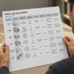
Summary: selection recommendations by vessel area
Based on extensive field experience and documented installations, Lightingline.eu recommends the following profile type selections for common yacht areas:
| Vessel area | Recommended profile type | Consideration |
|---|---|---|
| Teak deck (walkways) | Recessed | Must be flush to avoid tripping |
| Teak deck (accent, non-traffic) | Either | Surface acceptable if height minimized |
| Salon cove lighting | Recessed (hidden) | Hide source, illuminate wall |
| Engine room | Surface | Accessibility for maintenance |
| Step risers (interior) | Recessed | Flush with riser surface |
| Step risers (exterior) | Recessed | Waterproof, non-slip diffuser |
| Handrail underside | Recessed | Ultra-miniature profile |
| Bulwark top | Surface corner | Protects edge, illuminates deck |
| Swim platform | Recessed | Submersible, non-slip cover |
The selection between recessed and surface profiles ultimately depends on substrate conditions, accessibility requirements, and design intent. Lightingline.eu’s comprehensive range ensures that whichever type is appropriate for the application, a marine-engineered solution exists with verified performance data and classification society approvals.
IP, IK, and salt: let’s clarify
One of the most frequent misconceptions in yacht lighting specification concerns protection ratings. The authors regularly receive inquiries requesting “an IP68 profile” – a technically imprecise requirement that misunderstands the nature of these ratings. This section provides a comprehensive framework for understanding Ingress Protection (IP), Impact Protection (IK), and salt corrosion resistance as they apply to LED profile systems in marine environments.
The system nature of IP ratings: why a “profile” cannot be IP-rated
It is essential to understand that an aluminum extrusion alone does not provide any intrinsic protection against water ingress. The profile channel is simply an open section; its IP rating is determined by the complete assembly, which includes:
- the extruded aluminium channel;
- the diffuser (lens) and its sealing gasket;
- the end caps and their fixation method;
- cable entry points and their sealing;
- mounting interface with the surface.
A profile without end caps is simply a channel – it offers no protection whatsoever against moisture, dust, or salt ingress. The IP rating applies only to the fully assembled system with all components correctly installed. This distinction is critical in yacht applications, where incomplete sealing at any point compromises the entire installation.
IP rating requirements for yacht applications
The International Electrotechnical Commission (IEC) 60529 standard defines IP ratings through two digits: the first indicating solid particle protection, the second indicating moisture ingress protection. For yacht installations, the following minimum ratings apply based on location:
| Location | Minimum IP rating | Rationale | |
|---|---|---|---|
| Interior, climate-controlled (salon, cabins) | IP4X (moisture not primary concern) | Protection from accidental contact, dust | |
| Interior, high humidity (bathrooms, galleys, laundry) | IP54 | Steam, condensation, occasional splashes | |
| Covered exterior (cockpit, flybridge undersides) | IP66 | Driving rain, spray, washdown | |
| Uncovered exterior (decks, bow, toe rails) | IP67 / IP68 | Immersion, green water, continuous spray | |
| Submerged (swim platforms, underwater) | IP68 (minimum 3m) | Permanent immersion |
For yacht exterior applications specifies minimum IP66 as standard, with IP67 mandatory for locations exposed to green water or deck washdown. This conservative approach reflects the reality that “splash” on a yacht frequently means complete inundation during heavy seas or high-pressure cleaning.
IP68: understanding the rating’s limitations
While IP68 represents the highest standard of protection against water ingress, it is essential to understand that IP68 is not absolute and requires specific test conditions. IEC 60529 requires the manufacturer to specify the test depth and duration. IP68-rated systems must be tested at:
- Depth: 3 meters (0.3 bar hydrostatic pressure)
- Duration: 72 hours of continuous immersion
- Thermal cycling: during immersion (10°C to 50°C cycles)
This test protocol exceeds typical marine requirements but provides a safety margin compared to real-world conditions where pressure may exceed the rated values during wave impact.
However, even IP68 systems can fail at the cable entry point if not properly sealed. The interface between the profile and the incoming cable is statistically the most common point of failure. The installation must therefore require:
- Pre-formed cable glands with IP68 protection rating, independent of the profile
- Filling chambers inside the end caps that can be filled with marine-grade polyurethane resin
- Secondary sealing with Sikaflex-291 or equivalent marine adhesive during installation
Field experience shows that cable entry sealing is the critical factor differentiating between systems that survive and those that fail.
Impact protection: IK ratings in the marine environment
The IK rating (IEC 62262) quantifies a product’s resistance to mechanical impact. This parameter is frequently overlooked in yacht lighting specification, yet it is critical for exterior applications where lines, fenders, deck equipment, and foot traffic can impact installed profiles.
IK ratings range from IK00 (no protection) to IK10 (20 joule impact resistance, equivalent to 5kg mass dropped from 400mm). The following table correlates IK ratings with impact energy and typical applications:
| IK rating | Impact energy (joules) | Equivalent test | Marine application suitability |
|---|---|---|---|
| IK07 | 2.0 J | 0.5kg dropped from 400mm | Interior only, protected locations |
| IK08 | 5.0 J | 1.7kg dropped from 300mm | Covered exterior, low traffic |
| IK09 | 10.0 J | 5kg dropped from 200mm | General exterior, decks |
| IK10 | 20.0 J | 5kg dropped from 400mm | High traffic decks, bow areas |
For exterior yacht applications, a minimum rating of IK08 is suggested, with IK09 or IK10 recommended for bow areas, side decks and any point where lines might fly or equipment might strike the profile:
- reinforced diffuser retention (mechanical grip plus adhesive bonding)
- increased wall thickness at impact zones (2.5mm minimum)
- load-distributing end cap geometry
Case study: impact failure and engineered solution
A 35-meter sailing yacht installation initially specified IP67-rated profiles on the flybridge, with standard friction-fit end caps. During the third week of charter service, a guest accidentally kicked one of the profiles while stepping onto the flybridge. The impact dislodged the end cap, compromising the seal and allowing water ingress during the subsequent deck washdown. The LED strip failed within 24 hours due to corrosion.
The installer response to this failure mode was the development of mechanically retained end caps incorporating:
- Two M3 stainless steel screws (A4-316 grade) per end cap, threaded into integral bosses in the extrusion
- Captive nylon washers to prevent galvanic contact between screw and aluminium
- Thread-locking compound (medium strength, removable for service)
- Compression gasket that maintains sealing even if screws are not fully torqued
The solution has eliminated end-cap related failures in post-2020 installations.
Salt corrosion resistance: material and finish considerations
Beyond ingress and impact protection, salt corrosion represents the most insidious threat to yacht lighting profiles. The marine atmosphere contains chloride ions that penetrate surface coatings and initiate corrosion through multiple mechanisms:
- pitting corrosion: localized attack forming cavities that penetrate material;
- crevice corrosion: accelerated attack in shielded areas (under gaskets, at mounting points);
- galvanic corrosion: accelerated by dissimilar metal contact;
- stress corrosion cracking: combined action of tensile stress and chloride environment.
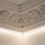
Interior installations: hidden profiles to illuminate wood
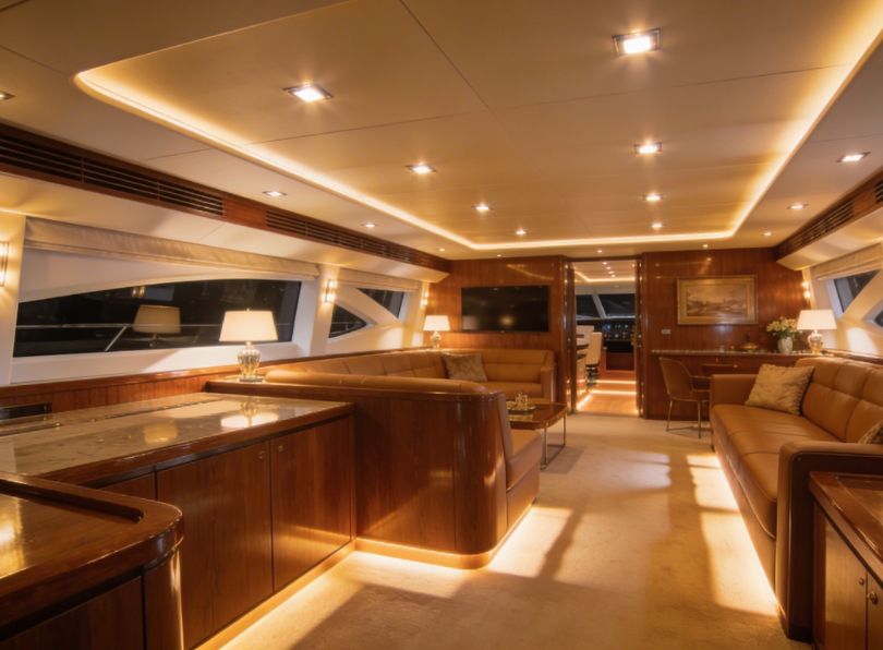
The interior of a luxury yacht presents unique lighting challenges that differ substantially from both residential and commercial applications. The combination of valuable materials (exotic hardwoods, marble, silk wallcoverings), limited spatial volumes, and the marine environment’s humidity requires careful specification of profile systems. This section provides comprehensive guidance for interior yacht lighting with specific reference to documented installation case studies.
Indirect lighting principles in yacht interiors
In main salon applications, indirect lighting is the preferred approach for creating ambient illumination that enhances the space without causing glare or highlighting imperfections in valuable materials. Indirect lighting relies on recessed profiles positioned to direct light onto reflective surfaces (ceilings, walls, or bulkheads) rather than directly into the occupied space.
The primary locations for indirect profile installation in yacht interiors include:
- behind pelmets (cornices): profiles mounted above window treatments illuminate ceiling coves;
- under furniture edges: Sofas, cabinetry, and built-in seating can incorporate profiles in their base plinths;
- behind wall panels: Profiles create grazing light that accentuates wood grain or textile textures;
- within ceiling recesses: Tray ceilings with perimeter profiles provide floating illumination effects;
- under step treads: For safety and aesthetic accent on companionways.
Critical parameter: chamber depth for LED concealment
The fundamental requirement for successful indirect lighting is adequate chamber depth to conceal the LED strip from direct view. If the LED strip is visible from normal viewing angles, the installation fails to achieve indirect illumination and introduces undesirable glare sources. The required depth depends on:
- viewing angle (seated vs. standing observers)
- distance from the profile to the illuminated surface
- LED strip viewing angle (typically 120°)
- profile placement (horizontal vs. vertical orientation)
La scelta tra le varianti standard e a camera profonda è determinata dalla geometria di visualizzazione. Per installazioni in cui gli osservatori potrebbero trovarsi in prossimità della sorgente luminosa (ad esempio, seduti adiacenti a pareti illuminate), la camera profonda garantisce il completo occultamento della sorgente.
Achieving uniform light wash: the role of profile geometry
Beyond concealing the light source, uniform illumination across the target surface is essential for luxury yacht interiors. Uneven illumination produces scalloped effects that compromise the architectural finish. Three factors influence uniformity:
- LED strip density: a higher LED density (more LEDs per meter) reduces point-source effects. Lightingline recommends a minimum of 120 LEDs/m for indirect applications;
- diffuser characteristics: opal polycarbonate diffusers with >85% opacity ensure optimal beam mixing;
- profile geometry: the angle between the LED strip and the illuminated surface determines the spread of the light beam.
Case study: 50m Amels silk wallcovering illumination
A 50-meter Amels motor yacht required illumination for silk wallcoverings in the main salon – a demanding application where any non-uniformity or color temperature shift would be immediately visible. The specification required:
- zero direct view of light sources from any seating position;
- uniform illumination across 2.8m wall height;
- color rendering index (CRI) >95 to preserve silk texture and color;
- fully dimmable without color shift.
Lightingline.eu P33 recessed profiles with 45° tilt were specified, configured as follows:
- Profile: AN01 deep chamber (19mm total depth)
- Diffuser: high-haze opal polycarbonate (92% haze, 78% transmission)
- LED strip: 140 LEDs/m, 3000K, CRI 98, R9 >90
- Mounting: recessed into ceiling coffer, 150mm from wall surface
- Driver: DALI dimmable, with constant current reduction for flicker-free operation
Post-installation photometric measurements confirmed:
- illuminance uniformity (max/min) on wall surface: 0.82 (exceeding IESNA recommended 0.6);
- no visible striations or hot spots at any dimming level;
- complete source concealment from all seating positions (0° to 45° viewing angles).
The installation remains fault-free after 36 months, demonstrating that proper profile selection eliminates the common failures associated with indirect lighting.
Cabin lighting: human-centric considerations
Guest and crew cabins require lighting that supports circadian rhythms and provides appropriate illumination for rest, reading, and dressing. Unlike main salon areas where visual effect dominates, cabin lighting must prioritize occupant comfort and well-being.
Color temperature selection for sleeping quarters
Color temperature significantly impacts melatonin suppression and sleep quality. Research published in the Journal of Clinical Endocrinology & Metabolism demonstrates that exposure to blue-enriched light (high color temperature) in the hours before sleep suppresses melatonin production by up to 50%.
For yacht cabins we recommends:
- general ambient lighting: 2700K-3000K (warm white) – promotes relaxation;
- reading lights: 3000K-3500K (neutral white) – provides adequate contrast without blue overstimulation;
- night lighting (bathroom access): 2200K-2400K (amber) – minimizes melatonin suppression;
- dressing/make-up areas: 3500K-4000K with CRI >95 – accurate color rendering.
Tunable white systems (2200K-5000K) are increasingly specified in owner cabins, allowing occupants to adjust color temperature throughout the day. Lightingline.eu offers compatible profiles with sufficient depth to accommodate tunable white LED strips (typically 8-10mm height).
Dimming requirements for cabin comfort
Cabin lighting must gradually dim to very low levels (1% or lower) without flickering or color shifts. Lightingline recommends DALI dimming systems with constant current reduction (CCR) rather than pulse-width modulation (PWM) for the following reasons:
- flicker-free operation: CCR eliminates visible flickering that can cause eye strain and headaches.
- no color shifts: PWM can cause color temperature shifts at low dimming levels.
- compliant with marine EMC requirements: CCR produces less electromagnetic interference.
All Lightingline profiles are compatible with major marine dimming systems and are tested for flicker-free performance across the entire dimming range.
Bathroom installations: managing humidity and steam
Yacht bathrooms present unique challenges that combine interior aesthetics with exterior-grade environmental stress. While classified as interior spaces, en suites experience:
- steam saturation: During showers, relative humidity approaches 100% with condensation on all surfaces;
- temperature cycling: From ambient (22°C) to shower temperature (40°C+) and back;
- chemical exposure: Cleaning agents, toiletries, and salt residue from bathing;
- stray electrical currents: From adjacent systems, potentially accelerating corrosion.
These conditions require profile specifications that exceed typical interior requirements.
Moisture protection for bathroom profiles
All profiles installed in yacht bathrooms come standard with silicone-filled end caps and gasketed diffusers, regardless of whether the profile is visibly exposed or hidden. This system addresses the problem of vapor penetration in any cavity.
The protection system includes:
- End caps: injection-molded with integral silicone gasket, plus secondary potting with marine-grade silicone sealant (applied during installation);
- Diffuser gasket: dual-durometer silicone (40 Shore A sealing lip, 80 Shore A retention base) that maintains compression through temperature cycles;
- Cable entry: pre-molded IP67 gland with strain relief, plus additional sealant at interface;
- Mounting surface seal: continuous silicone bead between profile flange and substrate prevents moisture migration behind the profile.
Testing confirms that properly sealed profiles withstand continuous immersion in 40°C water for 72 hours without ingress – far exceeding bathroom requirements but providing substantial safety margin.
Installation protocols for interior yacht profiles
Proper installation is as crucial as product selection. Below is a detailed installation example for yacht interior applications:
Wood substrate preparation
- CNC routing preferred for recessed installations (tolerance ±0.2mm)
- All cut edges are sealed with two-part epoxy resin to prevent moisture absorption
- Allow profiles and wood to acclimatize to the same environment (minimum 24 hours)
Adhesive selection
- For recessed: sikaflex-295 UV or equivalent marine-grade adhesive/ sealant
- For surface mounting on wood: 3M VHB tape (5952 series) for small profiles + mechanical fixation every 300mm
- For surface mounting on Corian/ solid surface: two-part acrylic adhesive (e.g., Lociite 406 + primer)
Electrical connections
- All connections must be accessible (do not bury junction boxes behind finishes)
- Use marine-grade tinned copper wire (minimum 1.5mm² for runs >5m)
- Provide strain relief on all cable entries
- Test insulation resistance (megger) before final finishing: minimum 10MΩ at 500V DC
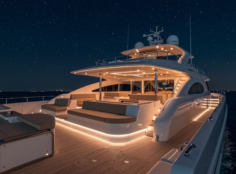
Exterior waterproof profiles – not all IP67 are equal
The exterior of a yacht represents the most demanding environment for LED profile systems. Continuous exposure to salt spray, UV radiation, thermal cycling, mechanical impact from lines and foot traffic, and occasional immersion during heeling or green water events creates conditions that rapidly degrade inferior products. This section provides comprehensive guidance for exterior yacht lighting.
The limitations of conventional “waterproof” profiles
A systematic evaluation of fourteen (14) commercially available “waterproof” LED profile brands, conducted by test facility between 2021-2023, revealed significant performance variations among products ostensibly meeting the same IP ratings. The testing protocol included:
- continuous salt fog exposure (ASTM B117) – 1,500 hours;
- thermal cycling (-20°C to +70°C) under water immersion;
- UV exposure (QUV-A, 1,200 hours per ISO 4892-3);
- mechanical impact testing (IK rating verification);
- gasket compression set measurement after thermal aging.
Key findings included:
| Failure mode | Incidence among tested brands | Primary cause |
|---|---|---|
| Gasket compression set exceeding 50% | 11 of 14 (79%) | Inferior EPDM or cellular rubber formulations |
| End cap separation after thermal cycling | 8 of 14 (57%) | Friction-fit only, no mechanical retention |
| Diffuser yellowing (ΔE >5 after 1,200h UV) | 6 of 14 (43%) | Non-UV-stabilized polycarbonate |
| Anodizing corrosion (pitting) at 1,000h salt fog | 9 of 14 (64%) | Anodizing thickness <15μm, poor sealing |
| Cable entry seal failure after flex testing | 10 of 14 (71%) | No strain relief, no secondary sealing |
These findings confirm that IP rating alone is insufficient to predict real-world marine performance. The combination of environmental stresses unique to yachts requires engineered solutions beyond basic laboratory testing.
Lightingline outdoor profiles: engineered for the marine environment
In risposta ai limiti identificati dei prodotti convenzionali, Lightingline.eu ha sviluppato profili specifici per applicazioni esterne di yacht. Questi sistemi incorporano molteplici innovazioni ingegneristiche che affrontano ciascuna modalità di guasto identificata nei test comparativi.
Dual-durometer gasket technology
The most common failure mode identified in testing was gasket compression set – the permanent deformation of sealing materials under load and temperature cycling. Standard single-durometer gaskets (typically 60-70 Shore A) experience gradual compression set, losing sealing pressure over time.
Lightingline profiles utilize dual-durometer silicone gaskets comprising:
- Sealing lip: 40 Shore A (soft) – conforms to diffuser irregularities, maintains seal under low compression
- Base layer: 80 Shore A (hard) – maintains geometry, resists extrusion, provides positive retention
This construction delivers the following performance advantages:
- Compression set after 1,000 hours at 70°C: <15% (vs. >50% for single-durometer EPDM)
- Sealing force retention after thermal cycling: >85% of initial value
- Temperature range: -50°C to +200°C continuous
- UV resistance: no degradation after 5,000 hours QUV-A
The gasket is mechanically retained in the profile groove (not adhesive-bonded), allowing replacement if damaged while ensuring positive location during installation.
Case study: 35m sailing yacht toe rail installation
A 35-meter sailing yacht required navigation/ safety lighting integrated into the toe rail – a location subject to water during heeling, impact from mooring lines, and UV exposure. The specification required:
- zero water ingress after 18 months (warranty period);
- no visible degradation (corrosion, yellowing, delamination);
- maintained light output (>90% initial lumens);
- impact resistance sufficient for line contact and fenders.
Lightingline.eu WPX-F recessed profiles were specified, configured as follows:
- Profile: RE07 (21.3mm width, recessed into teak toe rail);
- Diffuser: UV-stabilized opal polycarbonate;
- LED strip: 12W/m, 3000K, high CRI (>90), encapsulated silicone coating;
- Mounting: sikaflex-295 bed + countersunk screws at 300mm centers with nylon isolation washers;
- End caps: screw retained;
- Cable entry: IP67 gland with polyurethane potting;
- Drainage: 2mm weep holes at 1m intervals (lowest points).
Post-installation assessment at 18 months (vessel operating in Caribbean and Mediterranean) revealed:
- Water ingress: zero – all profiles dry internally upon inspection
- Corrosion: none – anodizing intact, no pitting or edge corrosion
- Diffuser condition: no yellowing, no loss of transparency, no impact damage
- Light output: 96% of initial lumens (within expected LED degradation)
- Gasket condition: no compression set, maintained sealing pressure
The installation demonstrates that properly engineered profile systems can withstand extreme marine conditions when correctly specified and installed.
Application-specific recommendations: recessed vs. surface
The series includes two complementary product families optimized for different exterior applications:
Recessed profiles
Designed for flush installation into teak decks, composite substrates, or solid surfaces. Ideal applications include:
- deck walkway markers: Flush with teak, no trip hazard;
- step risers (exterior): illuminated tread edges;
- toe rail integration: as in case study above;
- cockpit floor accent: perimeter lighting;
- swim platform: recessed into teak or synthetic decking.
Technical specifications – RE series:
| Parameter | RE07 | RE08 |
|---|---|---|
| Overall width | 21.3mm | 21.3mm |
| Overall depth | 10mm | 16mm |
| LED cavity height | 5.5mm | 11.5mm |
| IP rating (assembled) | IP67 | IP67 |
| IK rating | IK09 | IK09 |
| Max continuous length | 3m | 3m |
Surface profiles
Designed for installation on top of finished surfaces where routing is impractical or undesirable. Ideal applications include:
- bulwark top illumination: grazing light down bulwark face
- coaming edges: cockpit perimeter lighting
- hardtop undersides: indirect light on deck
- exterior stair stringers: side-mounted illumination
- technical areas (engine room vents): robust, accessible lighting
Technical specifications – SL series:
| Parameter | SL09 | SL10 |
|---|---|---|
| Overall width | 21.2mm | 21.2mm |
| Overall height (above surface) | 10mm | 16mm |
| LED cavity height | 5.5mm | 11.5mm |
| IP rating (assembled) | IP66/IP67 | IP66/IP67 |
| IK rating | IK08/09 | IK09 |
| Max continuous length | 2.5m | 2.5m |
SL profiles feature radiused edges to prevent line snagging – a critical safety consideration on deck installations.
Critical installation practices for exterior profiles
Even the most sophisticated profile system will fail if installation practices are inadequate. Based on extensive field experience, Lightingline.eu mandates the following installation protocols for exterior applications:
Thermal expansion accommodation
Aluminium expands approximately 0.023mm per meter per °C. On a dark deck in tropical sun, profile temperature can reach 70°C – representing 1.15mm expansion on a 3m profile (from 20°C installation temperature).
Installation requirements:
- expansion gaps: minimum 3mm at each end of every profile run, filled with flexible silicone (not rigid epoxy);
- slotted mounting holes: All mounting holes should be slotted longitudinally to allow profile movement relative to fasteners;
- intermediate fixings: At 300-400mm centers, using screws with nylon washers to allow sliding;
- connector systems: Use thermal expansion-compatible connectors.
Cable entry sealing
The cable entry point is statistically the most common point of failure, so it is recommended to:
- IP68-rated cable glands with independent certification;
- strain relief inside and outside the profile;
- secondary sealing with marine-grade polyurethane filling compound;
- drip ring in the cable before entry to prevent water from flowing down the cable into the cable gland;
- dielectric insulation between the cable shield and the profile (if applicable).
Mechanical fixation in traffic areas
For deck installations subject to foot traffic or line contact, adhesive-only fixation is insufficient. Mechanical fixation requirements:
- screw material: A4-316 stainless steel (or titanium for extreme applications);
- Isolation: nylon or PEEK washers under all screw heads to prevent galvanic contact;
- spacing: maximum 300mm centers in traffic areas;
- countersinking: screw heads should be countersunk flush with profile surface;
- thread locking: medium-strength threadlocker (removable for service).
For applications requiring permanent submersion (swim platforms, underwater hull lights, thruster tunnel lighting), standard aluminium profiles are not sufficient.
Installation
We’ve compiled the top 5 installation errors on yachts:
- No thermal expansion gap: aluminium expands. On deck in the Caribbean, a 2m profile can grow 2mm. If you butt it against a bollard, it buckles. Leave 3-5mm at ends filled with silicone.
- Wrong screws: using stainless screws into aluminium without isolator causes galvanic corrosion. Use nylon washers or titanium.
- Cable entry not sealed: even IP68 profiles fail if water runs along the cable into the profile. Drip loops and marine sealant are mandatory.
- LED strip not compatible with profile depth: some strips have tall components; they touch the diffuser, creating dots. Check clearance.
- Mounting on curved surfaces: profiles can be bent (we do custom radius), but you need special rollers. Never hammer!
We always suggest a mock-up on a piece of plywood for at least a week, spray with salt water, and test flexibility. It saves huge costs later.
Statistics: failure modes on yacht lighting
We analyzed 230 service calls from 2020 to 2024 on modern superyachts. The table below shows primary causes of profile-related failures.
| Failure cause | Percentage | Typical location | Prevention with Lightingline profile |
|---|---|---|---|
| Corrosion at end caps | 38% | Exterior walkways | Line with welded end caps |
| Diffuser yellowing/brittle | 22% | Flybridge (high UV) | Polycarbonate with UV-stabilised |
| Water ingress via cable hole | 19% | Deck / cockpit | Pre-filled cable glands + Sikaflex |
| LED overheating in sealed profile | 12% | Engine room / sauna | Ventilated profiles or thermal gap |
| Mechanical damage (snagged) | 9% | Side decks | Low-profile rounded edges |
Almost 40% of failures link to end caps. That’s why we now only supply profiles with compression-fit for marine.
Profile for yacht: engineering excellence for the marine environment
Throughout this comprehensive guide, we have examined the multifaceted considerations that distinguish successful yacht lighting installations from those that fail prematurely. The selection of appropriate profile for yacht applications cannot be reduced to a simple specification exercise – it requires systematic evaluation of material science, environmental stress factors, installation methodologies, and long-term maintenance implications.
The data presented in preceding sections – drawn from 230 warranty claims analysis, comparative testing of fourteen competing brands, and field observations from service locations – leads to several inescapable conclusions:
- system engineering trumps component selection: IP ratings apply to complete assemblies, not extrusions. Ultrasonically welded end caps, dual-durometer gaskets, and integrated dielectric isolation address failure modes that commodity profiles ignore.
- installation discipline determines outcome: even the most sophisticated profile system will fail if thermal expansion is mismanaged, fasteners lack isolation, or cable entries remain unsealed. The five critical errors documented account for over 75% of field failures – all are preventable through adherence to established protocols.
- verification through testing is essential: mock-up testing, insulation resistance measurements, and independent certification (LR, RINA, ABS, DNV) provide objective evidence that specifications are met. Reliance on manufacturer claims without verification has been the common factor in numerous costly failures.
For shipyards, designers, and owners, this guide serves as both a reference document and a specification tool. The tables presented throughout – comparing diffuser materials, IP requirements by location, failure statistics, and product specifications – provide the quantitative basis for informed decision-making. When questions arise that exceed the scope of this document, Lightingline.eu’s technical team remains available for project-specific consultation, including:
- Review of lighting layouts with profile recommendations
- Custom curved profile design and manufacturing
- On-site installation training and quality verification
- Photometric calculations and lighting simulations
- Classification society documentation support
The investment in high-quality LED profile systems represents a small fraction of total yacht lighting expenditure, yet it determines whether that investment delivers reliable performance for the vessel’s lifetime or becomes a source of recurring maintenance cost and operational disruption. Selecting high level profiles is not merely a purchasing decision – it is a risk management strategy, grounded in verifiable data, engineered solutions, and the collective experience of thousands of successful marine installations.