In this article…
- Why led voltage drop matters more than you think
- The physics of led voltage drop, forward voltage explained
- Led voltage drop by colour: the complete reference chart
- Voltage drop in led strips: how copper resistance creates the problem
- Formulas: how to calculate led voltage drop step by step
- Practical voltage drop calculator tables for 12V and 24V strips
- Maximum run lengths for led strips at 12V and 24V
- 12V vs 24V vs 48V: which system minimises led voltage drop?
- Wiring strategies for long led strip installations
- Aluminum led profiles and their role in voltage stability
- Choosing the right led strip for your run length
- How to measure led voltage drop with a multimeter
- Troubleshooting: identifying and fixing voltage drop in existing installations
- Standards, tolerances and acceptable voltage drop levels
- Temperature effects on led voltage drop
- Led drivers and power supplies: constant voltage vs constant current
- Step-by-step DIY installation guide for long led strip runs
- Commercial and architectural applications: large-scale voltage drop management
- FAQ — Frequently asked questions
- Mastering LED voltage drop for perfect, professional LED installations
Why led voltage drop matters more than you think
The term “LED voltage drop” appears frequently in LED installation guides, electrician forums, and LED manufacturer datasheets, but it actually encompasses two completely distinct, yet closely related, phenomena. These phenomena are often confused, leading to confusion and, ultimately, costly installation errors. The first phenomenon is the forward voltage drop of a single LED diode: the intrinsic electrical characteristic of a semiconductor junction that determines how much voltage the device consumes when emitting light. The second is the resistive voltage drop across the copper traces and power conductors of an LED strip: a purely physical consequence of Ohm’s Law, which affects the resistance of the current-carrying conductor over a given distance. Both forms of LED voltage drop are real, both are important, and both must be understood and managed for any LED strip installation to function properly, safely, and with consistent, professional-quality results.
The practical consequences of unmanaged LED voltage drop are immediately visible and can be frustrating: an LED strip that starts bright white at the power end but fades to a warm yellow at the other end; RGB LED strips where the color balance varies along the strip because the red, green, and blue channels experience different voltage drops; recessed lighting installations where one corner of a room shines brightly while the opposite corner appears noticeably darker; or storefronts where uneven backlighting makes the product display appear amateurish rather than professional. In all these cases, the underlying cause is the same: excessive voltage drop across too high a resistor, due to too high a current, over too far.
What makes this topic particularly relevant today is the explosion in the use of high-power LED strips for architectural, commercial, and residential lighting. Modern LED strips, especially high-density, high-CRI professional grade ones, draw significantly more current per meter than simple decorative strips of a decade ago, making voltage drop a much more complex engineering challenge. At the same time, the advent of 24V and 48V constant voltage systems, advanced constant current LED drivers, and the widespread availability of high-quality aluminum LED profiles have provided installers and designers with a comprehensive set of tools to solve the problem, provided they understand the physics and apply the right solutions. This article provides everything you need to make informed decisions, from fundamental physics to practical wiring diagrams and product specifications.
Market context: the growing importance of LED voltage drop management
The global LED strip market was valued at approximately USD 4.2 billion in 2024 and is projected to exceed USD 7.8 billion by 2030, growing at a compound annual growth rate of approximately 10.8% (source: MarketsandMarkets, 2024). This growth is driven by increasing adoption of LED strips in architectural cove lighting, hospitality signage, retail display, under-cabinet kitchen lighting, staircase illumination, and outdoor facade lighting. In all of these applications, run lengths are increasing, hospitality designers routinely specify continuous strip runs of 20–50 metres, while retail installations often require uniform backlighting across walls of 10–30 metres or more.
As run lengths increase, the led voltage drop problem scales proportionally. A survey of professional lighting installers conducted by the Lighting Industry Association (LIA, UK) in 2023 found that voltage drop-related problems, including visible dimming gradients, colour shift in RGB installations, and premature LED failure, accounted for approximately 34% of all service calls related to LED strip lighting in the 12 months prior. This figure underscores the enormous practical relevance of the subject: knowing how to calculate, predict, and eliminate led voltage drop is not an academic exercise but a fundamental professional skill that directly affects project quality and client satisfaction.
Among the professionals most affected are electricians, lighting designers, interior architects, audio-visual integrators, shopfitters, and kitchen fitters, all of whom routinely install LED strips as part of their work. For each of these professionals, a solid understanding of led voltage drop theory, combined with practical knowledge of the right products and wiring techniques, translates directly into better projects, fewer callbacks, and stronger reputations. The following sections build that understanding systematically, from first principles through to advanced installation strategies.
The physics of LED voltage drop — Forward voltage explained
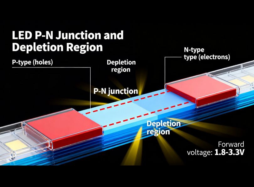
To truly understand led voltage drop, it is necessary first understand what an LED actually is at a physical level, and why it inevitably “drops” voltage as current flows through it. A light-emitting diode is a semiconductor device constructed from two layers of doped semiconductor material, an n-type layer (with excess electrons) and a p-type layer (with excess holes, i.e., absence of electrons), joined at a boundary known as the p-n junction. When a voltage is applied across the device in the forward direction (positive terminal to p-side, negative to n-side), electrons from the n-region and holes from the p-region migrate toward the junction, recombine, and in doing so, release energy in the form of photons — light. This process is called electroluminescence.
The semiconductor junction and forward voltage
The voltage drop across an LED, technically called the forward voltage (Vf), is not arbitrary. It is physically determined by the band gap energy of the semiconductor material used to construct the diode. The band gap energy is the minimum energy required for an electron to jump from the valence band to the conduction band of the semiconductor material. Since the energy of each photon of light is directly proportional to its frequency (E = hf, where h is Planck’s constant and f is the photon frequency), and since photon frequency is inversely proportional to wavelength (f = c/λ, where c is the speed of light and λ is the wavelength), it follows directly that LEDs emitting shorter wavelengths (higher-energy blue/violet photons) require higher forward voltages than LEDs emitting longer wavelengths (lower-energy red/infrared photons). This is a fundamental law of quantum mechanics, not a design choice or a manufacturing limitation.
The relationship between LED colour, semiconductor material, and forward voltage can be expressed qualitatively as follows. Infrared LEDs, which emit the lowest-energy photons, require forward voltages as low as 1.2V. Red LEDs, using aluminium gallium arsenide (AlGaAs) or gallium arsenide phosphide (GaAsP) junctions, require approximately 1.8–2.2V. Amber and yellow LEDs, using aluminium indium gallium phosphide (AlInGaP) junctions, require approximately 2.0–2.4V. Green LEDs, typically also using AlInGaP or Gallium Phosphide (GaP), require approximately 2.0–3.5V depending on the specific alloy composition and whether they are using “classic” green or the high-efficiency InGaN green. Blue and white LEDs, which use Indium Gallium Nitride (InGaN) junctions, require the highest forward voltages of the visible spectrum at approximately 2.8–3.6V. Ultraviolet LEDs require still higher voltages, up to 4.0–4.5V.
For white LEDs, by far the most common type used in LED strips, the forward voltage is typically specified between 2.8V and 3.4V per individual LED die, with a nominal value around 3.0–3.2V at rated current. It is crucial to understand, however, that white LEDs are not separate quantum entities emitting white light directly. Instead, they are invariably blue InGaN LEDs coated with a phosphor layer (typically cerium-doped yttrium aluminium garnet, or Ce:YAG) that converts a portion of the blue emission to yellow, with the combination of remaining blue and generated yellow appearing white to human vision. The forward voltage of the resulting white LED is therefore that of the underlying blue InGaN junction — approximately 3.0–3.2V — regardless of the colour temperature of the white light produced (2700K warm white, 4000K neutral white, or 6500K cool white all use the same underlying blue chip, hence the same forward voltage).
The LED I-V characteristic curve
Unlike resistors, which have a linear relationship between voltage and current described simply by Ohm’s Law (I = V/R), LEDs are fundamentally non-linear devices. Their behaviour is described by the Shockley diode equation, also known as the ideal diode equation:
Where:
- I = diode current (Amps)
- I₀ = reverse saturation current (typically 10⁻¹⁵ to 10⁻¹⁰ A for LEDs)
- V = voltage across the diode (Volts)
- n = ideality factor (typically 1–2 for real diodes; approximately 1.5–2.0 for LEDs)
- Vt = thermal voltage = kT/q ≈ 0.026V at room temperature (25°C), where k is Boltzmann’s constant, T is absolute temperature in Kelvin, and q is the electron charge
The practical implication of this exponential relationship is that the forward voltage of an LED is very strongly dependent on current, but over the normal operating range (around the rated current), the Vf varies only slightly. When you apply a voltage slightly below the threshold (approximately 2.0–2.5V for a blue InGaN LED), essentially no current flows. As you increase voltage beyond the threshold, current rises extremely steeply — a difference of just 0.1–0.2V can double or triple the current. This is why LEDs are never driven directly from a voltage source without current limiting: the near-vertical I-V curve means that any slight overvoltage results in catastrophically high current and immediate LED destruction.
In practice, the I-V curve of an LED in the operating region appears quasi-linear and can be approximated by a model with two components: an ideal voltage source equal to the threshold voltage (Vth) in series with a small dynamic resistance (rd). For a white LED at 20mA, Vth ≈ 3.0V and rd ≈ 5–10 Ohms, giving Vf ≈ 3.0 + (0.020 × 7) = 3.14V. This two-component model is very useful for hand calculations of LED circuit design and is extensively used by electronics engineers designing LED driver circuits.
Temperature dependence of forward voltage
One of the most important and most practically relevant characteristics of LED forward voltage is its significant temperature dependence. For virtually all LED types, forward voltage decreases as junction temperature increases. The temperature coefficient of forward voltage (dVf/dT) for InGaN LEDs (white, blue, green) is approximately −1 to −4 mV per degree Celsius. For AlInGaP LEDs (red, amber, yellow), it is slightly higher at approximately −2 to −5 mV/°C.
This means, for example, that a white LED with Vf = 3.15V at 25°C may have Vf ≈ 2.95V at 85°C — a reduction of approximately 0.2V or about 6%. At first glance this might seem trivially small, but it has significant practical consequences. In a constant-voltage LED strip, lower Vf at elevated temperature means higher current draw, because the current-limiting resistors on the strip are fixed, and the LED junction itself now presents less resistance to current flow. Higher current at higher temperature creates more heat, which further reduces Vf, which drives even more current, a positive feedback loop known as thermal runaway. In a well-designed strip with adequate thermal management (such as mounting in an aluminum profile), the junction temperature stabilises well before runaway occurs; in a poorly designed or poorly mounted strip, this cycle can lead to premature LED degradation or failure.
This temperature effect on led voltage drop is the primary reason why aluminum LED profiles are not merely aesthetic accessories but genuine engineering components that contribute meaningfully to the electrical stability, colour consistency, and longevity of LED strip installations. By conducting heat away from the LED junction and distributing it over the profile’s surface area, aluminum profiles keep junction temperatures low, maintaining Vf close to its cold-start value and preventing thermal runaway. We will return to this topic in detail in Section 10 on aluminum profiles.
Forward voltage in multi-LED configurations
LED strips do not consist of individual LEDs connected one by one across the supply voltage; that arrangement would make each LED’s operating point almost impossible to control. Instead, LED strips invariably use a configuration where small groups of LEDs, typically 3 LEDs in series, are connected across the supply through a current-limiting resistor. This series-group approach is universal and explains several important characteristics of LED strips.
In a group of 3 white LEDs in series, the total forward voltage across the LED group is 3 × Vf ≈ 3 × 3.1V = 9.3V (at rated current). The current-limiting resistor then drops the remaining voltage: for a 12V supply, the resistor drops 12 − 9.3 = 2.7V. Since the group typically draws 20mA, the resistor value is 2.7V / 0.020A = 135 Ohms (commonly approximated to 150 Ohms in practice). For a 24V supply, a typical group uses 6 LEDs in series: 6 × 3.1V = 18.6V across the LEDs, and the resistor drops 24 − 18.6 = 5.4V, giving a resistor of 5.4V / 0.020A = 270 Ohms.
This configuration has profound implications for voltage drop tolerance: a 24V strip with 6 LEDs in series can tolerate a much larger absolute voltage drop along its length before the LED current falls noticeably. If the supply end receives 24V and the far end receives 22.8V (a 5% drop, 1.2V), the 24V group reduces its resistor voltage from 5.4V to 4.2V — the LED current falls from approximately 20mA to approximately 15.6mA, a reduction of about 22%. For a 12V strip with 3 LEDs in series, a 5% drop means 0.6V less voltage: the resistor voltage falls from 2.7V to 2.1V, and the current falls from 20mA to approximately 14mA, a reduction of about 30%. This quantitative comparison shows that 12V strips are proportionally more sensitive to a given percentage of voltage drop than 24V strips, making 24V the preferred choice for all but the shortest runs.
LED voltage drop by colour: the complete reference chart
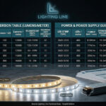
One of the most frequently searched topics in LED lighting is the LED voltage drop chart, a reference listing the expected forward voltage for each LED colour. Understanding the voltage for each LED colour is essential both for circuit design (selecting correct resistors and power supply voltages) and for troubleshooting (understanding why different-colour LEDs in an RGB strip can behave differently under voltage stress). The following table provides comprehensive reference data.
LED forward voltage by colour and semiconductor material
| LED colour | Wavelength (nm) | Semiconductor material | Typical Vf at 20mA | Range Vf | Relative voltage drop |
|---|---|---|---|---|---|
| Infrared (IR) | 850–940 | GaAs, AlGaAs | 1.2–1.5V | 1.1–1.8V | Lowest |
| Red | 620–750 | AlGaAs, GaAsP | 1.8–2.2V | 1.6–2.4V | Very Low |
| Red-Orange | 610–620 | AlInGaP | 2.0–2.3V | 1.9–2.5V | Low |
| Amber / Yellow | 570–620 | AlInGaP, GaAsP | 2.0–2.4V | 1.9–2.6V | Low–Medium |
| Yellow-Green | 555–570 | GaP, AlInGaP | 2.1–2.5V | 2.0–2.8V | Medium |
| Green (classic) | 520–555 | GaP, AlInGaP | 2.0–3.0V | 1.9–3.2V | Medium |
| Green (InGaN high-eff.) | 510–530 | InGaN | 2.8–3.3V | 2.6–3.5V | High |
| Blue | 450–490 | InGaN | 3.0–3.5V | 2.8–3.7V | High |
| Violet | 400–450 | InGaN | 3.2–4.0V | 3.0–4.2V | Very High |
| White (warm, 2700–3500K) | Broadband | InGaN + phosphor | 2.9–3.3V | 2.7–3.5V | High |
| White (neutral, 4000K) | Broadband | InGaN + phosphor | 3.0–3.4V | 2.8–3.6V | High |
| White (cool, 6000–6500K) | Broadband | InGaN + phosphor | 3.0–3.5V | 2.9–3.6V | High |
| UV (365–405nm) | 315–405 | InGaN, AlGaN | 3.5–4.5V | 3.2–5.0V | Highest |
Why the red LED has the lowest voltage drop
The red LED voltage drop is the lowest among visible-light LEDs, typically 1.8–2.2V, because red photons have the lowest energy among visible colours. The energy of a photon is E = hc/λ. For red light at λ = 660nm: E = (6.626 × 10⁻³⁴ × 3 × 10⁸) / (660 × 10⁻⁹) = 3.01 × 10⁻¹⁹ J = 1.88 eV. In electron-volts, this directly corresponds to the required junction forward voltage, confirming the theoretical prediction that the voltage drop across a red LED should be approximately 1.8–1.9V at threshold. The small additional voltage above threshold in practical devices arises from the ohmic resistance of the semiconductor bulk material, contact resistance, and wire bonding resistance.
Why the white LED has the highest voltage drop among common strip types
The white LED voltage drop of approximately 3.0–3.4V is the highest among the LED types used in common strip lighting applications, because (as explained in Section 2) white LEDs are fundamentally blue InGaN LEDs, and blue photons at λ ≈ 450nm require: E = hc/λ = (6.626 × 10⁻³⁴ × 3 × 10⁸) / (450 × 10⁻⁹) = 4.42 × 10⁻¹⁹ J = 2.76 eV. Hence the theoretical threshold forward voltage for a blue InGaN LED is approximately 2.76V, with practical values of 3.0–3.5V accounting for device resistance. The phosphor conversion process that creates white light from the blue emission does not affect the electrical characteristics of the junction, the voltage drop for white LED is determined entirely by the blue InGaN junction, not by the colour of the emitted light. This is confirmed by the fact that 2700K, 4000K, and 6500K white LEDs from the same manufacturer using the same InGaN chip platform will all have essentially identical forward voltage specifications.
Green LED voltage drop: two distinct technologies
The green LED voltage drop is particularly interesting because it depends critically on which semiconductor technology is used. “Classic” green LEDs, manufactured since the 1970s using Gallium Phosphide (GaP) or Aluminium Indium Gallium Phosphide (AlInGaP), have relatively modest forward voltages of 2.0–2.5V. However, high-efficiency modern green LEDs, required for high-quality RGBW strips and professional stage lighting, use InGaN junctions and have Vf values of 2.8–3.3V, much closer to blue. This distinction matters enormously for RGB LED strip design: a red-green-blue strip using InGaN green will have far more balanced forward voltages across its three channels (R: 2.0V, G: 3.1V, B: 3.2V) than one using GaP green (R: 2.0V, G: 2.2V, B: 3.2V), which is important for consistent colour mixing behaviour under varying voltage conditions.
Yellow LED voltage drop in the context of LED strips
The yellow LED voltage drop of approximately 2.0–2.4V places yellow LEDs in the low-to-medium range. Yellow-amber LEDs based on AlInGaP chemistry are used in signal lighting, some architectural amber-effect strips, and occasionally in tunable white strips that mix white and amber channels to simulate candle-like colour temperatures (1800–2200K). Because their Vf is significantly lower than blue/white LEDs, special consideration is needed when mixing yellow/amber LEDs with white LEDs in a single strip run, the resistor values must be calculated separately for each colour channel to ensure both channels draw equal currents and the colour balance remains stable as supply voltage varies.
LED voltage drop chart: typical values at different currents
| LED Type | Vf at 5mA | Vf at 10mA | Vf at 20mA | Vf at 30mA | Vf at 50mA | Vf at 100mA (high-power) |
|---|---|---|---|---|---|---|
| Red (AlGaAs) | 1.65V | 1.75V | 2.0V | 2.1V | 2.2V | 2.4V |
| Amber (AlInGaP) | 1.75V | 1.90V | 2.1V | 2.2V | 2.35V | 2.5V |
| Green (GaP classic) | 1.85V | 2.0V | 2.2V | 2.3V | 2.5V | 2.7V |
| Green (InGaN) | 2.6V | 2.8V | 3.1V | 3.2V | 3.35V | 3.5V |
| Blue (InGaN) | 2.7V | 2.9V | 3.2V | 3.35V | 3.5V | 3.7V |
| White (warm/neutral) | 2.7V | 2.85V | 3.1V | 3.25V | 3.4V | 3.6V |
| White (cool) | 2.75V | 2.9V | 3.15V | 3.30V | 3.45V | 3.65V |
Notice that in all cases, forward voltage increases slightly with current, this is consistent with the diode equation, since higher current requires a higher forward bias to drive more charge carriers across the junction. The increase is relatively modest within the normal operating range, which is why LED strips based on constant-voltage designs with resistor current limiting work tolerably well even when supply voltage varies by a few percent.
Voltage drop in LED strips: how copper resistance creates the problem
Having established the physics of individual LED forward voltage, we now turn to the second, and for most practical installations, more immediately important, form of led voltage drop: the resistive voltage loss that occurs along the copper traces and supply cables of an LED strip as current flows from the power supply to the LEDs distributed along the strip’s length. This type of voltage drop is not a property of the LEDs themselves but of the conductors connecting them, and it follows straightforwardly from Ohm’s Law: V = I × R.
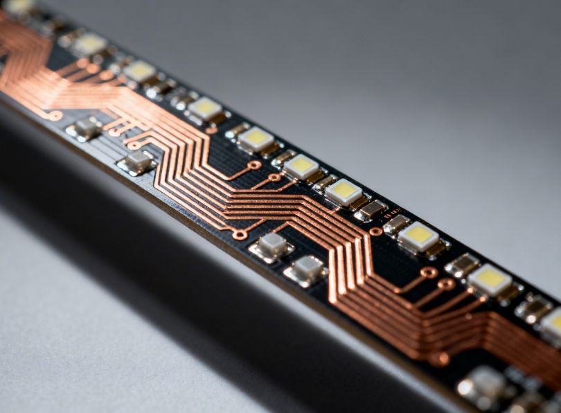
Structure of an LED strip: understanding the conductors
A typical SMD LED strip consists of a flexible PCB (printed circuit board) made from polyimide (Kapton) or polyester substrate, on which the LED chips are soldered at regular intervals. The PCB carries copper traces, the printed conductors that distribute electrical power from the input terminals to the LED groups along the strip’s length. These copper traces are the source of resistive voltage drop.
The resistance of a copper trace depends on three factors: the resistivity of copper (ρ = 1.72 × 10⁻⁸ Ω·m at 20°C), the cross-sectional area of the trace (width × thickness), and the length of the trace. For a typical LED strip, the copper layer is 1 oz/ft² (approximately 35 μm thick), and traces are typically 0.8–1.5mm wide. This gives a cross-sectional area of approximately 35 × 10⁻⁶ m × 1.0 × 10⁻³ m = 3.5 × 10⁻⁸ m². The resistance per metre of a single trace is therefore:
Since current must flow down the positive trace and return through the negative trace, the total round-trip resistance of the strip’s copper traces is approximately 2 × 0.49 = 0.98 Ω/m for a standard single-colour strip. For the wider traces found on higher-quality strips (1.5mm wide or 2oz copper), this can be reduced to approximately 0.3–0.5 Ω/m round-trip. For comparison, a 1.5mm² supply cable has a resistance of approximately 0.012 Ω/m round-trip, some 40 times less than the strip’s own traces, illustrating that in LED strip applications, the strip’s internal trace resistance often dominates over the feed cable resistance for anything beyond the very first few metres.
How the resistive voltage drop distributes along the strip
The current drawn by the LEDs is not concentrated at one point but is distributed along the entire length of the strip. This makes the strip’s electrical behaviour equivalent to what engineers call a distributed resistive-load transmission line, a subtly different situation from a simple series resistor with a point load at the end.
In a distributed-load strip, the current in the positive trace is highest at the input end (where it equals the total strip current) and decreases along the length (as LED groups draw their current off the trace). Similarly, the current in the negative (return) trace is zero at the far end and increases progressively back toward the power supply. The voltage at any point along the strip is therefore:
Where: x = distance from input (m), r = trace resistance per metre per conductor (Ω/m), I_total = total strip current (A), and i_per_unit_length = current draw per unit length (A/m). The quadratic correction term accounts for the fact that sections of the positive trace near the far end carry less current than sections near the input. In practice, for moderate strip lengths (≤10m), this term is small and the simpler linear approximation is adequate. For very long runs, the exact distributed model gives a voltage drop at the far end that is approximately half of what a naive “all current all the way to the end” calculation would suggest.
Practical resistance values for common LED strip types
| Strip type | Voltage | Power (W/m) | Current (A/m) | Typical trace resistance (Ω/m round-trip) | Voltage drop per metre at full load (mV/m) |
|---|---|---|---|---|---|
| Low-density SMD2835, 60 LED/m | 12V | 4.8W/m | 0.4A/m | 0.80 Ω/m | 320 mV/m |
| Standard SMD2835, 120 LED/m | 12V | 9.6W/m | 0.8A/m | 0.80 Ω/m | 640 mV/m |
| High-power SMD5050, 60 LED/m | 12V | 14.4W/m | 1.2A/m | 0.80 Ω/m | 960 mV/m |
| Standard SMD2835, 120 LED/m | 24V | 9.6W/m | 0.4A/m | 0.80 Ω/m | 320 mV/m |
| High-density SMD2835, 240 LED/m | 24V | 19.2W/m | 0.8A/m | 0.60 Ω/m* | 480 mV/m |
| Ultra-high-power COB, 480 LED/m | 24V | 20W/m | 0.83A/m | 0.50 Ω/m* | 415 mV/m |
| High-power SMD5630, 120 LED/m | 24V | 28.8W/m | 1.2A/m | 0.60 Ω/m* | 720 mV/m |
* Higher-power strips often use wider or thicker copper traces to manage heat and reduce resistance. Premium strips may use 2oz copper (70μm) instead of standard 1oz (35μm), halving trace resistance.
The cumulative effect: why long runs cause visible dimming
The voltage drop values in the table above, expressed in mV/m, may seem small in isolation, but they accumulate over run length. Consider a 5-metre run of high-power 12V SMD5050 strip (14.4W/m, 1.2A/m). The total current drawn is 1.2 × 5 = 6A. Using the simplified linear model (adequate for this run length), the voltage drop at the far end is approximately:
This cannot be right: we cannot have 12V of drop in a 12V system. The error is in the model: we used the full 6A as if it flows the entire 5m, but in reality it decreases along the strip (the distributed load model). The correct approach uses the average current method: since current decreases linearly from 6A at the input to 0A at the end of the positive trace, the average current is 3A, and the resistance of the 5m positive trace is 0.40 Ω/m × 5m = 2.0 Ω (using half of 0.80 Ω/m for one conductor). So:
This is still extreme, a 50% voltage drop over 5 metres! This is the reality for a very high-power 12V strip: a 14.4W/m, 12V strip on a 5-metre run is an extremely challenging case for voltage drop, and in practice would require either parallel power injection from both ends or a switch to 24V supply. The 5-metre single-feed limit commonly cited by strip manufacturers assumes much lower-power strips (typically ≤7.2W/m for 12V).
For a more moderate case: 5-metre 12V strip at 4.8W/m (0.4A/m), total current 2A, average current 1A, trace resistance per conductor 0.40 × 5 = 2.0 Ω:
Even for this relatively low-power strip, 5 metres produces a 16.7% voltage drop, far beyond the 5% design target. This illustrates why manufacturer-stated maximum run lengths for single-feed are typically 3–5 metres for 12V systems and 7–10 metres for 24V systems, and why power injection strategies are essential for anything longer.
Formulas: how to calculate LED voltage drop step by step
Calculating led voltage drop accurately requires combining two sets of calculations: the voltage drop across the supply cables (from power supply to strip input), and the voltage drop along the strip’s own copper traces. In practice, for typical installations with reasonably short, adequately sized feed cables, the feed cable drop is small and the strip trace drop dominates. The following formulas cover both components and are the standard tools used by professional lighting designers and electricians worldwide.
Voltage drop in the feed cable
The voltage drop in the cable from the power supply to the LED strip is a simple series resistor problem. The cable carries the full strip current at all points from PSU to strip input terminal:
= (1.72×10⁻⁸ × 2 × L_cable) / (A_cable_m²)For copper cable in practical units:
R_cable (Ω) ≈ 0.0344 × L_cable (m) / A_cable (mm²)Therefore:
V_cable (V) = I_total (A) × 0.0344 × L_cable (m) / A_cable (mm²)
Example: power supply feeds a 12V LED strip via 3m of 1.5mm² twin cable. Total strip current = 4A.
V_cable = 4A × 0.0688Ω = 0.275V
Percentage drop = 0.275/12 × 100% = 2.3% → Acceptable
Voltage drop along the LED strip traces
As established in Section 4, the distributed-load nature of the strip means that for a strip fed from one end, the voltage at any point x along the strip is:
– i_per_m = current draw per metre of strip (A/m)
– r_trace = round-trip trace resistance per metre (Ω/m)
– L_total = total strip length (m)
– x = distance from input to the point of interest (m)The voltage at the far end (x = L_total):
V_far = V_input − i_per_m × r_trace × L_total² / 2
This quadratic formula is the exact result for a uniform distributed load. For quick estimates, many engineers use the simpler “full current all the way” approach with a correction factor of 0.5:
– I_total = i_per_m × L_total (total strip current, A)
– R_trace_total = r_trace × L_total (total round-trip trace resistance, Ω)
Worked example: complete voltage drop calculation for a 5-metre 24V strip
– supply voltage: 24V
– strip: 12W/m, 24V, SMD2835 144LED/m
– strip current per metre: 12/24 = 0.5 A/m
– strip trace resistance: 0.60 Ω/m (round-trip)
– strip length: 5m
– feed cable: 2m of 1.5mm² copper twinStep 1: Feed cable voltage drop
I_total = 0.5 × 5 = 2.5A
R_cable = 0.0344 × 2 / 1.5 = 0.0459 Ω
V_cable = 2.5 × 0.0459 = 0.115V → 0.48% of 24V ✓ ExcellentStep 2: Strip trace voltage drop (far end)
V_trace = 0.5 × I_total × R_trace_total
R_trace_total = 0.60 × 5 = 3.0 Ω
V_trace = 0.5 × 2.5 × 3.0 = 3.75V ???This gives only 24 − 0.115 − 3.75 = 20.14V at far end → 16% drop → NOT acceptableAction required: use power injection at mid-point or feed from both ends.If fed from both ends (symmetric):
Each half draws I_half = 2.5/2 = 1.25A from each end
Effective length = 2.5m per side
V_trace_half = 0.5 × 1.25 × (0.60 × 2.5) = 0.5 × 1.25 × 1.5 = 0.94V
Far end (mid-point) receives: 24 − 0.115 − 0.94 = 22.95V → 4.4% drop ✓ Acceptable
The LED voltage drop calculator formula summarised
| Quantity to calculate | Formula | Units |
|---|---|---|
| Total strip current | I = P_total / V_supply = (W/m × L) / V | Amperes (A) |
| Cable resistance (round-trip) | R_cable = 0.0344 × L_cable / A_cable | Ohms (Ω) |
| Cable voltage drop | V_cable = I × R_cable | Volts (V) |
| Strip trace resistance (total) | R_trace = r_trace/m × L_strip | Ohms (Ω) |
| Strip voltage drop (far end, one-end feed) | V_strip = 0.5 × I × R_trace | Volts (V) |
| Total voltage drop | V_total = V_cable + V_strip | Volts (V) |
| Percentage voltage drop | %VD = (V_total / V_supply) × 100 | Percent (%) |
| Voltage at far end | V_far = V_supply − V_total | Volts (V) |
| Maximum run length (one-end feed, x% limit) | L_max = √(2 × (x/100 × V) × V / (W/m × r_trace)) | Metres (m) |
Forward voltage drop across a single LED: the resistor calculation
When designing circuits with individual LEDs (not strips), or when troubleshooting a strip circuit, knowing how to calculate the voltage drop across a LED in series with a current-limiting resistor is fundamental:
I_LED = V_resistor / R_limitFor a series group of n LEDs:
V_resistor = V_supply − (n × V_f)
R_limit = (V_supply − n × V_f) / I_targetExample: 3 white LEDs in series, 12V supply, 20mA target
V_f per LED = 3.1V
V_resistor = 12 − (3 × 3.1) = 12 − 9.3 = 2.7V
R_limit = 2.7 / 0.020 = 135 Ω (use 150Ω standard)
Practical voltage drop calculator tables for 12V and 24V strips
The following reference tables allow you to quickly estimate the voltage drop at the far end of a single-feed LED strip run for a range of common strip power ratings, supply voltages, and run lengths. These tables use the exact distributed-load formula (V_drop = 0.5 × I_total × R_trace_total) with typical trace resistance values. Use them for initial estimates; always verify with exact values from your specific strip’s datasheet before finalising a design.
Assumptions: trace resistance = 0.80 Ω/m round-trip for 12V strips, 0.60 Ω/m for 24V strips. The percentage voltage drop is calculated relative to the nominal supply voltage. Green cells (≤3%) indicate excellent uniformity, cells with 3–5% indicate acceptable performance for decorative use, cells >5% indicate that power injection or redesign is required.
Voltage drop table: 12V LED strips (single-end feed)
| Strip power (W/m) | Current (A/m) | 2m Run | 3m Run | 4m Run | 5m Run | 7m Run | 10m Run |
|---|---|---|---|---|---|---|---|
| 4.8W/m | 0.40A/m | 0.13V / 1.1% | 0.29V / 2.4% | 0.51V / 4.3% | 0.80V / 6.7% | 1.57V / 13% | 3.20V / 27% |
| 7.2W/m | 0.60A/m | 0.19V / 1.6% | 0.43V / 3.6% | 0.77V / 6.4% | 1.20V / 10% | 2.35V / 20% | 4.80V / 40% |
| 9.6W/m | 0.80A/m | 0.26V / 2.1% | 0.58V / 4.8% | 1.02V / 8.5% | 1.60V / 13% | 3.14V / 26% | 6.40V / 53% |
| 14.4W/m | 1.20A/m | 0.38V / 3.2% | 0.86V / 7.2% | 1.54V / 13% | 2.40V / 20% | 4.70V / 39% | 9.60V / 80% |
Voltage drop table: 24V LED strips (single-end feed)
| Strip power (W/m) | Current (A/m) | 3m Run | 5m Run | 7m Run | 10m Run | 15m Run | 20m Run |
|---|---|---|---|---|---|---|---|
| 4.8W/m | 0.20A/m | 0.054V / 0.2% | 0.15V / 0.6% | 0.29V / 1.2% | 0.60V / 2.5% | 1.35V / 5.6% | 2.40V / 10% |
| 9.6W/m | 0.40A/m | 0.11V / 0.5% | 0.30V / 1.3% | 0.59V / 2.4% | 1.20V / 5.0% | 2.70V / 11% | 4.80V / 20% |
| 14.4W/m | 0.60A/m | 0.16V / 0.7% | 0.45V / 1.9% | 0.88V / 3.7% | 1.80V / 7.5% | 4.05V / 17% | 7.20V / 30% |
| 19.2W/m | 0.80A/m | 0.22V / 0.9% | 0.60V / 2.5% | 1.18V / 4.9% | 2.40V / 10% | 5.40V / 22% | 9.60V / 40% |
| 24W/m | 1.00A/m | 0.27V / 1.1% | 0.75V / 3.1% | 1.47V / 6.1% | 3.00V / 12.5% | 6.75V / 28% | 12.0V / 50% |
These tables powerfully illustrate the fundamental advantage of 24V systems. At equal power per metre, a 24V strip draws exactly half the current of a 12V strip. Since voltage drop is proportional to current squared times resistance (P_loss = I² × R) or simply to I × R (voltage drop), halving the current halves the voltage drop in Volts. But since the nominal voltage is doubled, the percentage voltage drop is reduced to one-quarter of the 12V case. This is the engineering reason why 24V LED strips are always preferred for run lengths beyond 4–5 metres.
Maximum run lengths for LED strips at 12V and 24V
One of the most practically useful outputs of the voltage drop formulas is the maximum single-feed run length, the longest strip that can be fed from one end with a single set of power cables before the voltage drop at the far end exceeds the design limit. The following analysis uses the 5% voltage drop limit as the design target (suitable for decorative and residential applications);,tighter limits (3%) apply for commercial and museum-quality work.
Deriving the maximum run length formula
Setting the far-end voltage drop equal to the maximum allowed (x% of supply voltage) and solving for length:
V_drop_max = (x/100) × V_supplyUsing V_drop = 0.5 × (i_per_m × L) × (r_trace × L) = 0.5 × i_per_m × r_trace × L²
Setting equal to V_drop_max:
0.5 × i_per_m × r_trace × L² = (x/100) × V_supply
Solving for L:
L_max = √[2 × (x/100) × V_supply / (i_per_m × r_trace)]
L_max = √[2 × (x/100) × V_supply² / (W_per_m × r_trace)]
Maximum run length reference table
| Supply voltage | Strip power (W/m) | Trace R (Ω/m) | Max run (3% limit) | Max run (5% limit) | Max run (10% limit) |
|---|---|---|---|---|---|
| 12V | 4.8W/m | 0.80 | 3.7m | 4.7m | 6.7m |
| 12V | 7.2W/m | 0.80 | 3.0m | 3.9m | 5.5m |
| 12V | 9.6W/m | 0.80 | 2.6m | 3.4m | 4.7m |
| 12V | 14.4W/m | 0.80 | 2.1m | 2.7m | 3.9m |
| 24V | 4.8W/m | 0.60 | 10.6m | 13.7m | 19.4m |
| 24V | 9.6W/m | 0.60 | 7.5m | 9.7m | 13.7m |
| 24V | 14.4W/m | 0.60 | 6.1m | 7.9m | 11.2m |
| 24V | 19.2W/m | 0.60 | 5.3m | 6.8m | 9.7m |
| 24V | 24W/m | 0.55 | 4.9m | 6.3m | 8.9m |
| 48V | 9.6W/m | 0.50 | 24.0m | 31.0m | 43.8m |
| 48V | 19.2W/m | 0.50 | 17.0m | 21.9m | 31.0m |
These maximum run lengths assume single-end feeding and a uniform, fully loaded strip. In many practical installations, strips are not at 100% brightness (especially in dimmed systems), which reduces the current load and extends the effective maximum run length. A strip dimmed to 50% output draws approximately 50% of the rated current, meaning the voltage drop falls to approximately 50% of the full-load value, effectively doubling the usable run length.
Extended run lengths through power injection
For runs beyond the single-feed maximum, the most common and effective technique is power injection, supplying power to the strip at multiple points along its length, so that the maximum distance any LED is from a feed point is reduced. The voltage drop from each injection point to the most distant LED is then limited to a fraction of the full-run drop.
The two most common power injection methods are:
- dual-end feeding (both ends): the strip is connected to the power supply at both the start and the end. The current effectively flows into the strip from both ends and meets somewhere in the middle. The maximum effective half-length is L_total/2, reducing the worst-case voltage drop by a factor of 4 (because V_drop ∝ L²). This is simple to implement and highly effective for runs up to twice the single-feed maximum;
- mid-run injection: a parallel power cable runs alongside the strip from the PSU to the mid-point, where it connects to the strip’s power terminals. This splits the strip into two independent halves, each fed from one end. Maximum effective half-length is again L_total/2, with the same factor-of-4 improvement in voltage drop.
When a strip is fed at N+1 equally spaced points (N injection points plus the input), the effective maximum half-segment length is L_total / (2N+2), and the maximum voltage drop is reduced by a factor of (N+1)². For a single mid-point injection (N=1), the reduction is 4×. For two mid-point injections (N=2), the reduction is 9×. In practice, more than two additional injection points is unusual in residential/commercial work.
12V vs 24V vs 48V: which system minimises LED voltage drop?
The choice of supply voltage is the single most impactful design decision for managing led voltage drop in strip lighting installations. Understanding the quantitative differences between 12V, 24V, and 48V systems, and the trade-offs each involves, allows lighting designers and electricians to make optimal choices for each specific application.
The physics of voltage choice
For a given power output (Watts per metre), the relationship between supply voltage and current is: I = P/V. Doubling the voltage halves the current. Since resistive voltage drop is V = I × R, halving the current halves the absolute voltage drop in Volts. But since the supply voltage is also doubled, the percentage voltage drop falls to one-quarter. This quadratic improvement in percentage voltage drop with increasing supply voltage is the fundamental engineering argument for higher supply voltages in long LED strip installations.
Expressed as a design rule: percentage voltage drop ∝ (W/m) / V². A system at 24V with the same W/m as a 12V system has one-quarter the percentage voltage drop. A 48V system has one-sixteenth the percentage voltage drop of an equivalent 12V system. This is a remarkably powerful lever.
12V systems: advantages and limitations
12V is the traditional standard for LED strip lighting and remains the most commonly used supply voltage in residential and automotive applications. Its advantages include widespread compatibility with automotive batteries, solar systems, low-voltage landscape lighting infrastructure, and an enormous ecosystem of control gear, dimmers, and LED strips at very competitive prices.
The primary limitation of 12V systems is their high sensitivity to led voltage drop on any run longer than approximately 3–5 metres. A 12V strip drawing 1A/m will experience a 5% voltage drop in approximately 3.7 metres (for 0.80 Ω/m trace resistance). For most decorative strip applications where run lengths are 1–3 metres, under-cabinet lighting, furniture feature lighting, short cove sections, 12V is entirely adequate and the simplest, most cost-effective choice.
For LED strips that will be used in aluminum profiles (see Section 10), 12V is often an excellent choice because the profiles limit individual section lengths to 1–3 metres per section, which comfortably falls within the 12V voltage drop window, especially for profile-mounted strips that are then joined via separate power connections at each section.
24V systems: the professional standard for most applications
24V has become the professional standard for LED strip lighting in commercial, hospitality, retail, and higher-end residential applications. The quadrupling of voltage-drop performance compared to 12V dramatically extends the practical run length, reducing the need for multiple injection points and simplifying wiring substantially. For run lengths of 5–15 metres, 24V is almost always the correct choice.
Additionally, 24V strips typically use 6 LEDs in series per group (versus 3 for 12V strips), which improves the efficiency of the current-limiting resistors: the resistor drops 5.4V on a 24V system versus 2.7V on a 12V system, a larger share of supply voltage is usefully consumed by the LEDs rather than wasted in the resistors. This makes 24V strips intrinsically more energy-efficient per lumen as well as more tolerant of voltage variation.
48V systems: the future for long commercial runs
48V LED strip systems represent the emerging professional standard for demanding commercial applications requiring very long, continuous, uniform runs. At 48V, the percentage voltage drop advantage over 12V is sixteen-fold: a 48V, 10W/m strip can be run for over 30 metres from a single feed point before reaching a 5% voltage drop limit. This makes 48V strips ideal for long linear architectural installations in hotels, airports, shopping centres, and museums.
Additionally, 48V DC falls within the SELV (Safety Extra-Low Voltage) threshold defined by IEC 60449 as ≤50V DC, meaning that 48V systems can in many jurisdictions be installed without the conduit requirements and licensed electrician restrictions that apply to mains voltage systems, a significant practical advantage in retrofit and interior design projects.
The limitation of 48V systems is higher cost (48V power supplies and compatible dimmers are more expensive), less widespread availability of compatible control gear, and the fact that 48V strip components are still a less mature product category than 12V and 24V. However, the performance advantage for long commercial runs is unambiguous and the 48V category is growing rapidly.
Comparison table: 12V vs 24V vs 48V systems
| Parameter | 12V system | 24V system | 48V system |
|---|---|---|---|
| % Voltage drop at equal W/m (relative) | 16× (worst) | 4× (medium) | 1× (best) |
| Max single-feed run (10W/m, 5% limit) | ~3.8m | ~7.5m | ~30m |
| Resistor efficiency (LEDs in series/group) | 3 LEDs | 6 LEDs | 12–14 LEDs |
| Product availability | Very wide | Wide | Limited (growing) |
| Control gear cost | Low | Low,medium | Medium–High |
| SELV compliance (IEC) | Yes | Yes | Yes (≤50V DC) |
| Typical application | Short decorative runs, under-cabinet, profiles ≤2m | Most commercial/residential ≤15m | Long commercial, architectural, hospitality >15m |
| LED strip cost per metre | Low | Low, medium | Medium, high |
Wiring strategies for long LED strip installations
Understanding the physics and formulas of led voltage drop is only the first step; the real professional skill lies in choosing and implementing the correct wiring strategy for each specific installation scenario. This section presents the major wiring architectures used by professional lighting installers worldwide, with guidance on when each is appropriate and how to implement it correctly.
Strategy 1: single-end feed — Simple, limited range
The single-end feed is the simplest wiring configuration: the power supply connects to one end of the strip via a feed cable, and the strip is not connected at any other point. This is appropriate for short runs (up to the single-feed maximum run length established in Section 7) and is by far the most commonly installed configuration in residential applications.
When to use: 12V strips up to 3m, 24V strips up to 7m (for W/m values typical in residential use, ≤10W/m).
Cable sizing for single-end feed: size the feed cable to limit cable voltage drop to ≤1% of supply voltage. For a 5m, 24V strip at 10W/m, total current = 5 × (10/24) = 2.08A. Allowed cable drop = 0.01 × 24 = 0.24V. Required cable resistance: R = V/I = 0.24/2.08 = 0.115Ω. For a 2m cable run: A = 0.0344 × 2 / 0.115 = 0.60mm² → use 1.0mm² cable.
Strategy 2: dual-end feed — Doubles effective run length
In a dual-end feed, both ends of the strip are connected to the same power supply via separate feed cables. The current enters the strip from both ends and meets somewhere in the middle. For a symmetric load (uniform strip), the current from each end supplies half the strip, and the effective maximum half-length is L/2. The far-end voltage drop is reduced by a factor of 4 compared to single-end feeding.
Implementation note: both feed cables must connect to the same power supply, connecting to different power supplies creates a risk of circulating currents and is generally not recommended unless the supplies are properly synchronised. Connect both positive feeds to the PSU positive terminal and both negative feeds to the PSU negative terminal. Use identical cable lengths and cross-sections on both feeds for maximum symmetry.
When to use: 12V strips from 3m to 8m, 24V strips from 7m to 20m.
Strategy 3: mid-run power injection
For runs that exceed the dual-end feed capacity, or where the physical layout makes dual-end feeding impractical, mid-run power injection adds one or more intermediate feed points along the strip’s length. A parallel power bus (typically a heavy-gauge wire, e.g., 2.5mm² or 4mm² for high-current runs) runs from the power supply to each injection point, where it connects to the strip’s PCB via solder points or dedicated injection connectors.
Important wiring rule: the injection conductors must carry the full current from their injection point to the PSU, so they must be sized based on the segment current they supply, not the full strip current. For a 20-metre strip at 10W/m (24V) with a mid-run injection at 10m: each half draws 10 × (10/24) = 4.17A. Feed cables to each injection point must handle 4.17A continuously, requiring at minimum 1.0mm² cable for short runs and 1.5mm² for runs over 3m.
Strategy 4: star (home-run) distribution
In large-scale installations (hotels, retail, commercial offices), the star or home-run distribution topology is the professional standard for eliminating voltage drop entirely. In this architecture, a heavy-gauge power distribution bus (or a low-resistance copper bus bar) runs from the power supply to a central distribution point, from which individual feed cables connect directly to each strip segment. Each strip segment is powered independently from the distribution bus, so the voltage at the start of each segment is always the full supply voltage.
This topology eliminates inter-segment voltage drop issues entirely but requires more cable and installation effort. The distribution bus itself must be sized for the full aggregate current of all segments it serves. For a 50-metre installation of 24V, 10W/m strip divided into 5×10m segments: total current = 50 × (10/24) = 20.8A. The distribution bus must handle 20.8A continuously with no more than 1% drop, requiring at minimum 6mm² cross-section for a 10m bus run.
Strategy 5: multiple power supplies in parallel
For very long, high-power installations where a single large power supply is impractical or undesirable (e.g., for redundancy, or because the strips span different rooms), multiple power supplies can be positioned at strategic points along the installation, each feeding a local section of the strip. This is architecturally elegant and eliminates long high-current cable runs.
Critical wiring rule: When multiple power supplies feed sections of a continuous strip, the individual sections must be electrically isolated from each other, i.e., the strip PCB must be cut between sections, and each section fed exclusively by its designated PSU. Never connect the positive rail of one PSU to the positive rail of another PSU without proper load-balancing circuitry, doing so can create circulating currents and damage both supplies.
Strategy 6: constant-current LED drivers for long runs
All of the strategies discussed so far assume constant-voltage power supplies. An alternative approach, particularly suited to museum, gallery, and architectural applications requiring absolute brightness uniformity across very long runs, is to use constant-current LED drivers paired with LED strips designed for constant-current operation.
In a constant-current system, the driver regulates the current through the LED strip rather than the voltage across it. As the trace resistance causes the voltage to drop along the run, the driver automatically adjusts its output voltage upward to compensate, maintaining the specified current at every point. This completely eliminates brightness variation along the strip length, assuming the constant-current driver has sufficient output voltage compliance range to compensate for the full trace resistance of the strip.
The limitation of constant-current systems is that they require LED strips specifically designed and matched for constant-current operation, which are less universally available and more expensive than standard constant-voltage strips. They are also harder to dim and control. However, for critical applications requiring absolute uniformity, they are the technically superior solution.
Cable cross-section selection guide
| Current (A) | Max cable length for 1% drop (12V) | Cable required (12V) | Max cable length for 1% drop (24V) | Cable required (24V) |
|---|---|---|---|---|
| 1A | 6.9m | 0.5mm² | 13.9m | 0.5mm² |
| 2A | 3.5m / 1.0mm² → 7.0m | 1.0mm² | 6.9m / 1.0mm² → 13.9m | 0.75mm² |
| 4A | 1.0mm² → 3.5m | 2.5mm² | 1.5mm² → 5.2m | 1.5mm² |
| 8A | 2.5mm² → 2.2m | 6mm² | 2.5mm² → 4.3m | 4mm² |
| 16A | 6mm² → 2.2m | 10mm² | 6mm² → 4.3m | 6mm² |
Aluminum LED profiles and their role in voltage stability
Aluminum LED profiles, also known as LED channels, LED extrusions, or LED mounting profiles, are one of the most important product categories in professional LED strip installation, and their significance extends far beyond aesthetics. While the finished lighting appearance is undeniably more polished and professional when strips are mounted in aluminum profiles, the engineering contribution of these profiles to electrical performance and LED longevity is equally substantial and is deeply connected to the management of led voltage drop.
Thermal management and its effect on forward voltage
As established in Section 2, the forward voltage of LED junctions decreases as temperature increases (approximately −2 to −4 mV/°C for InGaN LEDs). In a constant-voltage LED strip, this temperature-dependent change in forward voltage is directly coupled to the current drawn by each LED group through the fixed current-limiting resistors. Lower Vf → more current → more heat → even lower Vf → even more current → a positive feedback loop. In a worst case, this leads to thermal runaway; in a more typical case, it leads to elevated operating temperatures, accelerated lumen depreciation (L70/L80 lifetime is reached sooner), and colour shift.
Aluminum LED profiles provide a low thermal resistance path from the LED’s solder pad (the primary heat exit point) through the PCB substrate, through the adhesive bond to the profile floor, and into the aluminum extrusion. The profile’s large surface area then dissipates heat by convection and radiation. In a properly mounted, well-specified aluminum profile, the LED junction temperature can be maintained 20–40°C lower than in an equivalent strip mounted directly on a plasterboard or wood surface. This temperature reduction:
- stabilises forward voltage closer to the cold-start specification, reducing current variation over the operating period;
- reduces the positive feedback tendency of the thermal runaway cycle;
- maintains more consistent and stable current consumption along the strip, which means more predictable and stable voltage drop along long runs;
- directly extends LED lifetime (Arrhenius degradation law: every 10°C reduction in junction temperature approximately doubles LED lifetime).
Types of aluminum profiles for LED strips
The LightingLine catalogue offers an extensive range of aluminum profiles for every LED strip application. Understanding the optical and thermal characteristics of each profile type helps in selecting the optimal product for each project:
Surface-mounted (top-emitting) profiles
Surface-mounted profiles sit proud of the mounting surface, with the LED strip inserted into the channel of the extrusion and covered by a diffuser cover. They are the most versatile profile type and are available in an enormous range of widths (8mm to 30mm+), depths (5mm to 20mm+), and cross-sectional shapes (flat, arched, recessed foot, high-diffuser). The aluminum body provides excellent thermal coupling to the mounting surface, maximising heat dissipation.
Recessed profiles
Recessed profiles are designed to be set into a routed slot in a surface (plasterboard, wood, stone, concrete), so that the finished installation is flush with the surrounding surface. This provides a particularly clean, architectural appearance and is widely used in ceilings, floors, staircases, and furniture. Recessed profiles require pre-planning at the construction stage but deliver outstanding visual results. Their thermal performance depends on the thermal conductivity of the surrounding surface material.
Corner profiles
Corner profiles are designed to direct LED strip light at 45° or 90° angles, enabling corner installations in kitchens, shelving units, architectural reveals, and display cases. Their angled geometry creates particularly effective task lighting and wash effects. Available in both surface-mount and recessed variants.
Pendant (suspended) profiles
Pendant profiles are designed to hang from ceilings via suspension cables or rods, creating floating linear luminaires. They typically emit light downward (task/ambient) and often also upward (indirect/ambient). The suspended form requires the power supply connection to travel along or within the suspension system. Voltage drop management is particularly important for pendant profiles as runs are typically 1–4m and aesthetics require uniformity.
Wing/shadowline profiles
Wing profiles incorporate flanges that overlap the mounting surface, creating a shadowline gap effect that can suggest floating surfaces, a popular architectural detail in modern commercial interiors. The floating visual effect works best with even, gradient-free illumination, making voltage drop management especially critical for these profiles.
IP-rated waterproof profiles
For bathroom, outdoor, kitchen, and wet-room applications, IP-rated profiles (typically IP44, IP65, or IP67) enclose the LED strip in a sealed, water-resistant extrusion. These profiles also affect thermal performance, sealed profiles provide less convective cooling, so thermal design is more critical and lower-power strips are generally recommended. Voltage drop behaviour is the same as for standard profiles, but the potential consequences of thermal runaway are greater in the sealed enclosure.
Profile selection and the thermal resistance chain
For optimal thermal and thus electrical stability, the complete thermal resistance chain from LED junction to ambient air must be minimised. Each interface in this chain contributes a thermal resistance:
| Interface | Typical thermal resistance | Notes |
|---|---|---|
| LED junction → LED solder pad | 2–5 K/W per LED | Determined by LED chip package design |
| LED solder pad → PCB copper plane | 1–3 K/W | Depends on PCB copper thickness and thermal via design |
| PCB base → Profile floor | 2–8 K/W per 10cm | Depends on adhesive thermal conductivity; thermal tape is best, double-sided foam is worst |
| Profile floor → Profile body | Negligible (same material) | Aluminum is highly conductive (160 W/m·K) |
| Profile body → Ambient air | 5–15 K/W (varies with profile surface area) | Larger profiles with higher surface area have lower thermal resistance |
Recommendation for optimal thermal performance: always use thermal conductive double-sided tape (minimum 1.0 W/m·K) rather than standard double-sided foam tape, which has a thermal conductivity approximately 50× lower. For high-power strips (>15W/m), use thermally conductive silicone paste or thermal epoxy in addition to mechanical securing. These measures can reduce the PCB-to-profile thermal resistance by 3–5 K/W, lowering junction temperatures by 15–25°C at full load — a significant benefit for both electrical stability (forward voltage) and LED longevity.
Profile cover types and their effect on light output
The diffuser cover fitted over the aluminum profile has no direct effect on voltage drop but significantly affects the optical output and therefore the choice of LED strip power (W/m) that is required to meet the target illuminance. Understanding this interaction helps avoid under-powering (insufficient light) or over-powering (excessive heat, accelerated degradation) the strip:
| Cover type | Typical light transmission | Diffusion level | Led visibility (hot spots) | Best for |
|---|---|---|---|---|
| Clear (transparent) | 92–95% | None | Individual LEDs clearly visible | Maximum output, tool lighting, visible installation as design element |
| Satin/frosted | 80–88% | Medium | Slight LED visibility at low density | General purpose, balanced output and diffusion |
| Opal (white diffuser) | 65–75% | High | LEDs not visible (uniform glow) | Architectural applications, display lighting, premium interiors |
| Microprism | 85–90% | Medium-High | Not visible | High efficiency with uniform diffusion |
| Blackout / opaque side cover | 0% | Blocks side emission | N/A | Controlling light spill in display cases, shelves |
The key implication for electrical design is that an opal cover requires a strip with approximately 30–35% more luminous output (lm/m) to deliver the same illuminance as a clear cover, which typically means either more LEDs/m or higher power/m, either of which increases the current draw and therefore the voltage drop per metre. When specifying strip power for a profile installation, always calculate the required strip lm/m output based on the specific cover transmission factor, then determine the W/m needed to achieve that output, and finally calculate the voltage drop based on that W/m value.
Choosing the right LED strip for your run length
The relationship between LED strip specifications and led voltage drop behaviour is central to making the correct product choice for any installation. The following guidance, supported by direct links to the LightingLine product catalogue, helps you navigate the key specification parameters that determine voltage drop performance.
LED chip type and density
The LED chip type (SMD2835, SMD3528, SMD5050, SMD5630, COB, etc.) and the chip density (LEDs per metre) together determine the power per metre and hence the current per metre at a given supply voltage. Higher density and/or larger/brighter chips = more current = more voltage drop. The trade-off is between light output, uniformity (higher density reduces hot spots), and voltage drop performance.
Voltage: 12V vs 24V product lines
When planning any installation with runs over 5 metres, always choose a 24V strip variant. The LightingLine catalogue carries most strip types in both 12V and 24V versions — for longer runs, the 24V version will always perform better from a voltage drop perspective.
For very high-power applications (>20W/m) at run lengths over 10 metres, 24V constant-current strips or 48V strips should be evaluated.
COB LED strips: special characteristics
COB (Chip-on-Board) LED strips represent a significant advancement in strip lighting technology that has important implications for voltage drop management. Instead of discrete SMD packages, COB strips use hundreds or even thousands of bare LED chips bonded directly to the PCB substrate in a continuous linear array. This construction provides:
- superior thermal management: the absence of chip packages means the LED dies are directly bonded to the substrate, reducing the junction-to-PCB thermal resistance and improving heat spreading. This keeps junction temperatures lower, stabilising Vf and reducing current variation due to thermal effects;
- better light uniformity: at 480+ effective LEDs/m, COB strips are essentially continuous light sources with no perceptible hot spots even at very close distances from the diffuser — ideal for aluminum profile applications;
- higher power per metre: COB strips are available at 10–25W/m in 24V versions, which is energetically demanding but manageable with 24V and appropriate run length limits.
Matching strip and profile for optimal performance
The most professional LED strip installations always match the strip type to the profile type, considering both mechanical fit and thermal-optical performance. The following table provides guidance:
| Profile type | Recommended strip width | Recommended power (W/m) | Recommended voltage | Cover type |
|---|---|---|---|---|
| Slim surface-mount (8–10mm) | 8mm PCB | 4–8W/m | 12V or 24V | Frosted or opal |
| Standard surface-mount (12–16mm) | 10–12mm PCB | 8–15W/m | 24V preferred | Frosted or opal |
| Wide surface-mount (18–24mm) | 12–20mm PCB | 12–24W/m | 24V | Opal or microprism |
| Slim recessed (under 6mm depth) | 8mm PCB | 4–8W/m | 12V or 24V | Flush frosted |
| Standard recessed | 10–12mm PCB | 8–15W/m | 24V preferred | Flush opal |
| Corner 45° | 8–10mm PCB | 6–12W/m | 12V or 24V | Angled frosted |
| Pendant linear | 10–20mm PCB | 10–20W/m | 24V | Opal both sides |
| IP65/IP67 waterproof | 8–10mm PCB | 5–10W/m max | 24V | Sealed diffuser |
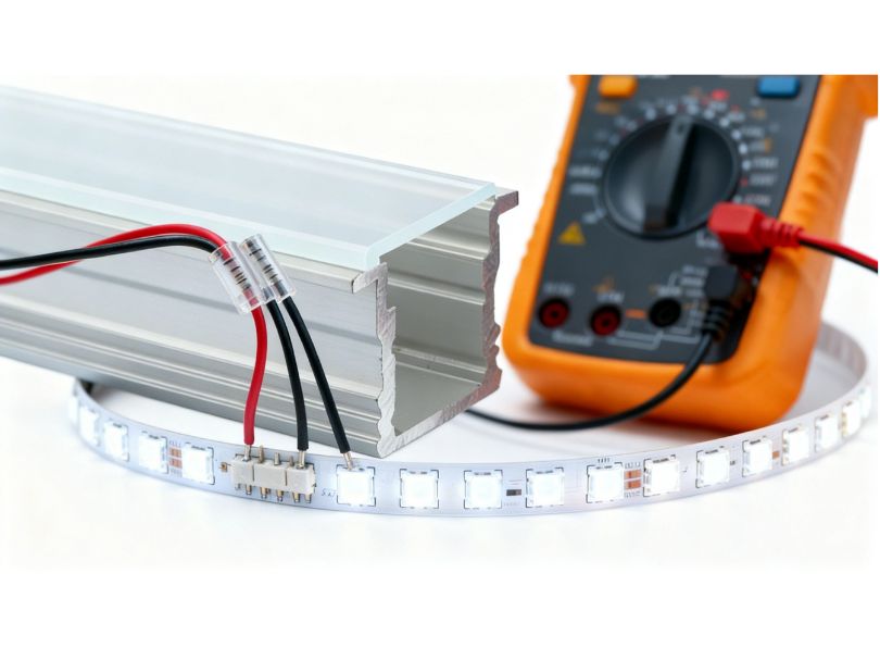
How to measure LED voltage drop with a multimeter
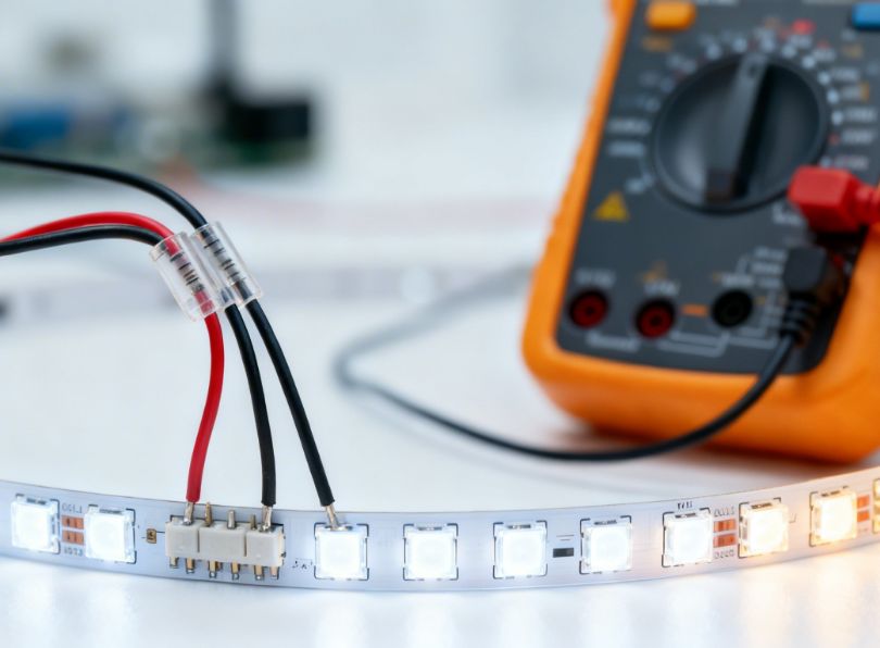
Knowing how to measure and verify led voltage drop in a real installation is an essential diagnostic skill for electricians, maintenance technicians, and advanced DIY installers. A basic digital multimeter with voltage measurement capability is all that is needed; no specialised equipment is required for most routine checks.
Measuring forward voltage of an individual LED
The most direct way to measure the forward voltage of an individual LED is to power it with a known current through a series resistor, then measure the voltage across the LED terminals with the voltmeter set to DC volts:
- construct a simple test circuit: 9V battery → 220Ω resistor → LED → return to battery. The resistor limits current to approximately (9 − Vf) / 220 ≈ (9 − 3) / 220 = 27mA for a white LED.
- connect the voltmeter probes across the LED (positive probe to anode, negative probe to cathode).
- read the DC voltage, this is the forward voltage Vf at the test current.
Note: Many modern multimeters have a “diode test” mode (usually indicated by a diode symbol). In this mode, the meter applies a small test current through the junction and displays the forward voltage. This is convenient but applies only a very small current (typically 1mA), so the measured Vf will be slightly lower than the datasheet value at rated current (e.g., 2.7V for a white LED in diode-test mode, vs 3.1V at 20mA).
Measuring voltage drop along an LED strip
To measure the actual voltage drop along an installed LED strip and verify it is within acceptable limits:
- turn on the LED strip at full brightness (100% duty cycle), and allow it to reach thermal equilibrium, typically 10–15 minutes;
- set the multimeter to DC volts, 20V range (for 12V) or 50V range (for 24V);
- measure the supply voltage at the power supply terminals (or at the very first point of the strip’s power input): record as V_start;
- without turning off the strip, measure the voltage at the far end of the strip — probe the positive (+) trace and the negative (−) trace at the last accessible LED group. Record as V_end;
- calculate voltage drop: V_drop = V_start − V_end;
- calculate percentage: %VD = (V_drop / V_supply_nominal) × 100.
Identifying excessive voltage drop visually
In many cases, excessive led voltage drop is immediately visible without instruments. Key visual indicators include:
- brightness gradient: the strip is noticeably brighter near the power supply and visibly dimmer at the far end, with a gradient rather than a step change;
- colour shift on white strips: in phosphor-converted white LEDs, current reduction due to voltage drop shifts the colour temperature warmer (more yellow), because the blue LED component dims more relative to the phosphor-converted yellow component. This is a very sensitive indicator, colour temperature shift may be visible before brightness change is perceptible;
- colour shift on RGB strips: red LEDs (lower Vf) are less affected by voltage drop than blue/green LEDs (higher Vf), so colour balance shifts toward warmer, more reddish tones at the far end of a long RGB run;
- flickering or instability: on very long, heavily loaded strips where the far end is receiving significantly reduced voltage, the LED groups there may operate near the threshold of their current-limiting resistors, causing sensitivity to any transient fluctuation in supply voltage.
Using a power meter for energy and current verification
A clamp meter (current clamp) allows non-invasive measurement of the current flowing in the supply cable to the strip. Comparing this measured current to the rated current (P_rated / V_supply) quickly confirms whether the strip is operating at the correct load. If measured current significantly exceeds rated current, the strip may be overloaded (e.g., wrong voltage or wrong power rating), if it is significantly lower, the strip may be undersupplied (excessive voltage drop or undersized PSU).
Troubleshooting: identifying and fixing voltage drop in existing installations
Even with careful design, led voltage drop problems can appear in installed systems, due to incorrect initial design, degradation of connections over time, accidental substitution of the wrong strip at a repair, or simply an underestimate of the actual run length or power density. The following systematic approach helps diagnose and correct these issues.
Diagnostic flowchart for voltage drop problems
When presented with a strip installation that shows uneven brightness or colour consistency, follow this diagnostic sequence:
- confirm the symptom pattern: is the dimming a gradient from one end (voltage drop) or a step change at a specific point (connection fault or damaged section)? A gradient suggests distributed voltage drop; a step change suggests a bad joint or cut-point connector;
- measure supply voltage at PSU terminals: with strip running. Confirm it is within ±5% of nominal. A low PSU output voltage is often the primary problem, the PSU is overloaded or its output adjustment has drifted;
- measure voltage at strip input terminals: compare to PSU terminal voltage. The difference is the feed cable drop. If >1%, the feed cable is undersized or too long;
- measure voltage at strip mid-point and far end: compare to input terminal voltage. This gives the strip trace voltage drop. Compare to theoretical expected value;
- if voltage drop is as expected (confirming the calculation was correct but the design was not adequate): implement one of the wiring strategies;
- if voltage drop is higher than expected: check for high-resistance joints, connectors, solder points, bare-wire connections. A resistive connector causes a local step drop in voltage; measure across each connector to identify the culprit. Clip-on LED strip connectors are particularly prone to high contact resistance over time, especially in humid or dusty environments.
Fixing high-resistance connectors
Clip-on connectors (sometimes called “hippo connectors” or “gapless connectors”) are convenient during installation but are a common source of elevated contact resistance in the field. Signs of a degraded connector include: visible discolouration or burning on the connector housing, a step change in brightness either side of the connector, or a measurable voltage drop of >0.1V across the connector under load.
Solution: replace clip connectors with properly soldered joints wherever long-term reliability is important. For solder connections, use flux-core solder (63/37 or 60/40), a temperature-controlled soldering iron at 320–360°C, clean the PCB pads with isopropyl alcohol before soldering, and keep thermal contact time brief (<3 seconds) to avoid PCB delamination. After soldering, cover exposed copper with clear nail varnish or acrylic conformal coating to prevent oxidation.
Upgrading feed cables
Where feed cable voltage drop is found to be excessive, the remedy is to replace the existing cable with one of larger cross-section. In a conduit or trunking installation, this may be straightforward. In a pre-plastered or permanently enclosed installation, it may be necessary to add a parallel supplementary feed cable running alongside the existing wiring. The combined resistance of two parallel cables is half the resistance of each individual cable, reducing the feed drop proportionally.
Retrofitting power injection points
For an existing installation where the strip trace drop is excessive and the strip is continuous (cannot be replaced without major disruption), the most practical retrofit solution is to add mid-run power injection. This requires:
- identifying an accessible point at approximately the mid-length of the strip;
- running a new parallel power cable from the PSU (or its terminal block) to that mid-point;
- connecting the new cable to the strip’s power pads at the mid-point, either by soldering directly to the PCB or using a compatible injection connector;
- verifying with measurements that the far-end voltage is now within acceptable limits.
Upgrading from 12V to 24V
For installations where the fundamental issue is that a 12V strip was specified for a run length more appropriate for 24V, the correct long-term solution is to replace the 12V strip with an equivalent 24V strip and upgrade the power supply. This requires:
- replacing the strip (all sections within the affected run);
- replacing the power supply with a 24V model of appropriate wattage;
- if a DALI, 0-10V, or RF/Wi-Fi dimmer is in use, verifying it is rated for 24V (most constant-voltage dimmers support both 12V and 24V);
- verifying all controller and cable ratings for the new voltage.
Standards, tolerances and acceptable voltage drop levels
Professional LED lighting installations must comply with applicable national and international electrical standards. The following overview covers the main standards relevant to led voltage drop management in LED strip lighting systems.
IEC and EN standards for low-voltage lighting systems
IEC 60364-5-52 (Electrical installations of buildings — Selection and erection of electrical equipment — Wiring systems) addresses voltage drop in low-voltage installations and requires that the voltage drop from the point of supply to the utilisation equipment (i.e., the LEDs) should not exceed 4% of the nominal voltage under maximum load conditions for lighting circuits, and 5% for other final circuits. For a 230V AC lighting circuit, this corresponds to ±9.2V. Note that this standard applies to the complete circuit from the main distribution board to the load — for LED strip lighting, it is the 230V AC supply side of the transformer/PSU that is covered, not the low-voltage DC side.
For the DC side of LED strip systems, the most relevant guidance comes from LED strip manufacturer specifications, which typically state maximum acceptable voltage drop in terms of percentage of supply voltage or absolute voltage (e.g., “do not exceed 10% voltage drop along strip length”). The widely adopted industry practice is ≤5% for decorative applications and ≤3% for professional applications.
DALI and 0-10V dimming system voltage requirements
When LED strips are controlled by DALI (Digital Addressable Lighting Interface) or 0-10V analogue dimming, additional voltage requirements apply. DALI bus voltage is nominally 16V DC with a minimum of 9.5V and maximum of 22.5V (IEC 62386-101). A DALI driver installed on an LED circuit must receive its control voltage within this range, excessive supply voltage drop can cause DALI communication errors in systems where the DALI bus is powered from the same supply as the LED strip. Maintain supply voltage within ±5% of nominal for DALI-controlled circuits.
LED driver standards: IEC 61347 and IEC 62384
IEC 62384 (DC or AC supplied electronic control gear for LED modules, performance requirements) specifies that constant-voltage LED drivers should maintain output voltage within ±5% of nominal under full load and within ±10% under no-load conditions. This standard implicitly limits the tolerable supply voltage range for LED strips to the extent that the driver complies with its nominal output tolerance.
The 3% rule in professional lighting design
While IEC standards set the minimum legal requirements, professional lighting design organisations (including the CIBSE in the UK, IESNA in the US, and DIN in Germany) recommend a more stringent 3% voltage drop limit for lighting circuits where uniformity and colour consistency are critical. The justification is that the human eye is more sensitive to lighting non-uniformity than many designers appreciate: a 5% voltage drop in a 12V system (0.6V) can produce a noticeable dimming gradient visible from across a room under typical ambient conditions.
For RGB and tunable white installations, the 3% limit is even more important, because colour imbalance caused by differential voltage drop across the R, G, and B channels can produce colour casts that are immediately obvious even to non-expert observers. Professional lighting designers specify a maximum 2–3% voltage drop for all colour-critical installations.
Temperature effects on LED voltage drop
The interaction between temperature and led voltage drop is one of the most subtle yet practically important aspects of LED system design. It affects not only the electrical behaviour of the LED junction (as discussed in Section 2) but also the resistance of the copper conductors, the performance of the power supply, and the long-term reliability of the entire installation.
Copper conductor resistance vs temperature
Copper has a positive temperature coefficient of resistance: its resistivity increases with temperature. The relationship is approximately linear over typical operating ranges:
– R₂₀ = resistance at 20°C (reference)
– α = temperature coefficient of copper ≈ 0.00393 per °C
– T = actual temperature (°C)Example: A copper trace with R = 0.80 Ω/m at 20°C:
At 60°C: R(60) = 0.80 × [1 + 0.00393 × 40] = 0.80 × 1.157 = 0.926 Ω/m
At 85°C: R(85) = 0.80 × [1 + 0.00393 × 65] = 0.80 × 1.255 = 1.004 Ω/m
This means that a strip operating at 85°C trace temperature (not unusual in a poorly thermally managed installation) experiences approximately 25% higher trace resistance than at 20°C, resulting in approximately 25% higher voltage drop for the same current. This further underscores the importance of thermal management through aluminum profiles: keeping the PCB temperature below 60°C reduces trace resistance and keeps voltage drop closer to the room-temperature design calculation.
Combined LED vf and copper resistance temperature effects
The two temperature effects, decreasing LED Vf (which increases current demand) and increasing copper resistance (which increases voltage drop per Ampere), act in the same direction: both worsen the effective voltage drop problem as temperature rises. This creates a scenario where an installation that appears to be within acceptable voltage drop limits at initial cold commissioning may develop visible brightness non-uniformity after 10–30 minutes of operation when the strip reaches thermal equilibrium.
Best practice: always design LED strip installations for thermal equilibrium conditions, not cold-start conditions. As a conservative rule of thumb, increase all current-per-metre values by 10% when calculating voltage drop for installed strips, to account for the combined effect of elevated temperature on Vf and trace resistance.
Ambient temperature effects on power supply output voltage
LED power supplies also have temperature-dependent output characteristics. Most constant-voltage LED drivers have a small positive temperature coefficient on output voltage, typically +0.03% per °C. This means that a PSU in a warm enclosure (e.g., above a kitchen ceiling, where ambient temperature can reach 40–50°C) may output 12.07–12.12V instead of the nominal 12V. This is generally helpful, providing a slight compensation for the voltage drop that would otherwise occur. However, for high-quality installations, it is better to locate PSUs in cool, well-ventilated locations to ensure stable, predictable output voltage.
LED drivers and power supplies: constant voltage vs constant current
The choice between a constant-voltage and constant-current LED driver is fundamental to the electrical design of any LED strip installation and directly determines how led voltage drop manifests and is managed.
Constant-voltage drivers
A constant-voltage LED driver (also commonly called a constant-voltage power supply, LED transformer, or LED PSU) maintains a fixed output voltage (e.g., 12V ±5% or 24V ±5%) regardless of the current drawn by the load, up to the rated maximum current. All standard LED strips with built-in current-limiting resistors are designed for constant-voltage operation. The driver supplies the nominal voltage, the strip’s resistors set the LED current, and voltage drop along the strip results in lower voltage (and hence lower current) at the far end.
In constant-voltage systems, the led voltage drop problem is inherently present and must be managed by limiting run lengths, using power injection, or upgrading to higher supply voltages, as detailed throughout this guide. The advantage of constant-voltage systems is their simplicity, low cost, and universal compatibility with standard LED strips.
Constant-current drivers
A constant-current LED driver maintains a fixed output current (e.g., 350mA, 700mA, or 1050mA) regardless of the voltage drop across the load, by continuously adjusting its output voltage to compensate. LED modules designed for constant-current operation (which use no internal current-limiting resistors, instead relying on the driver for current regulation) always receive the same specified current, regardless of how their forward voltage changes with temperature or manufacturing variation.
Constant-current systems eliminate voltage-drop-induced brightness variation in theory, but require LED strips specifically designed for constant-current operation. These strips connect all their LEDs in series, with the driver feeding the complete series string. The driver must have sufficient output voltage compliance to drive the total forward voltage of the string (n × Vf) plus any parasitic resistances. For long constant-current strip runs, the driver’s voltage compliance range must account for the total trace resistance as well.
Constant voltage vs constant current: comparison table
| Parameter | Constant voltage driver | Constant current driver |
|---|---|---|
| Typical application | Standard LED strips, all residential/commercial strip lighting | High-power module strings, museum/gallery, architectural precision |
| Strip compatibility | All standard constant-voltage LED strips | Only constant-current rated LED strips/modules |
| Voltage drop compensation | None, brightness varies with voltage drop | Automatic, current maintained despite voltage variations |
| Output voltage range | Fixed (e.g., 12V ±5%) | Variable (e.g., 8–40V compliance range) |
| Cost | Low–medium | Medium–high |
| Dimming compatibility | Wide (DALI, 0-10V, PWM, RF, Wi-Fi) | Limited (DALI, 0-10V for high-end types) |
| Multiple runs from one driver | Easy (parallel connection) | Complex (series connection or multiple drivers) |
| Led voltage drop sensitivity | High, requires careful run length management | Very low, automatic compensation |
Step-by-step DIY installation guide for long LED strip runs
This section provides a comprehensive, practical step-by-step guide for the DIY installer or tradesperson who wants to correctly plan and execute a long LED strip installation, one that avoids led voltage drop problems and produces professional results. Follow each step carefully, and cross-reference the formulas and tables in the earlier sections as needed.
Step 1: define your requirements
Before choosing any products, define the following:
- total run length (metres): measure the installation path carefully, including turns and any gaps required;
- required light output (lux or lm/m): determine based on the application (task lighting, accent, ambient);
- colour temperature: warm (2700–3000K), neutral (3500–4000K), or cool (5000–6500K) white; or RGB/tunable;
- CRI requirement: decorative (CRI ≥ 70), general commercial (CRI ≥ 80), professional/retail (CRI ≥ 90), museum (CRI ≥ 95);
- dimming requirement: on/off only, manual dimming, DALI, DMX, Wi-Fi/app control?
- installation location: dry interior, damp (bathroom/outdoor covered), wet (outdoor exposed)?
- profile type: surface, recessed, corner, pendant?
Step 2: select the LED strip
Based on requirements, select a strip that provides the target lm/m at the target power. Check the manufacturer’s datasheet for: voltage (12V or 24V), power per metre (W/m), current per metre (A/m), trace resistance per metre, and maximum rated run length per section.
As a starting point: for light output targets of 500–1000 lm/m, a 24V strip at 8–15W/m with a good CRI is typically appropriate. For accent and decorative applications, 4–8W/m is usually sufficient. For task lighting (under-cabinet, workbench), 12–20W/m may be needed, depending on the cover diffuser.
Step 3: choose the supply voltage
- Total run <3m: 12V is fine.
- Total run 3–10m: 24V strongly recommended.
- Total run >10m: 24V with injection, or 48V (if available).
Step 4: calculate voltage drop and determine wiring strategy
Using the formulas in Section 5, calculate the expected voltage drop at the far end for the planned single-end feed. If percentage drop exceeds 5%, plan power injection as described in Section 9. Document the wiring strategy before purchasing components.
Step 5: calculate total wattage and select the power supply
Select PSU rated at P_total × 1.25 (25% safety margin for thermal derating and inrush current)
For example: 10m of 24V, 10W/m strip: P_total = 100W. PSU rating: 100 × 1.25 = 125W. Select a 150W 24V PSU.
Step 6: select and size feed cables
Using the cable sizing table, select the minimum cable cross-section that limits feed cable voltage drop to ≤1% of supply voltage at the total strip current. Route feed cables and injection cables as directly as possible to minimise cable length.
Step 7: mount the aluminum profiles
Fix aluminum profiles to the mounting surface using the manufacturer’s recommended fixing method (screws through the profile floor, or clips for plasterboard). Ensure the profile is straight, secure, and properly positioned for the light distribution angle desired. If using recessed profiles, prepare the slot to the correct dimensions before profile installation.
Step 8: install the LED strip in the profile
Clean the profile floor with isopropyl alcohol to remove any grease or dust. Peel the backing from the strip’s 3M adhesive tape (or apply thermal double-sided tape to the profile floor if the strip uses a different adhesive). Press the strip firmly along the centre of the profile floor, ensuring full contact with no lifting or bubbles. For thermally critical applications, apply a small amount of thermal paste before pressing the strip down.
Step 9: make all electrical connections
Connect the feed cable to the strip’s input terminals at the power supply end. Make injection connections at planned mid-points. All connections should be soldered and insulated for a permanent installation; use clip connectors only for temporary or maintenance-accessible joints. Ensure correct polarity (+ to +, − to −) at every connection point.
Step 10: connect the power supply and test
Before fitting diffuser covers or closing any enclosure, power up the installation and verify:
- all LEDs illuminate (no dead sections);
- brightness and colour appear uniform along the full run;
- measure V_start and V_end. Confirm %VD is within design limit;
- after 15 minutes of operation, check for any sections that appear significantly brighter or dimmer than at startup (indicating thermal effects).
Step 11: fit diffuser covers and complete the installation
Once verified, cut diffuser covers to length (scoring and snapping, or cutting with a fine-tooth saw), and press them into the profile channel. Fit end caps on profile ends. Verify final appearance of the installation from the designed viewing angles.
Commercial and architectural applications: large-scale voltage drop management
In large commercial and architectural LED strip installations (hotel corridors, retail stores, airports, museums, shopping centres) the challenges of led voltage drop management are dramatically amplified by the scale of the installation. Individual strip runs may be 20–50 metres, total wattage may be several kilowatts, and the requirement for absolute uniformity of colour and brightness across the entire installation is non-negotiable for the client’s brand and visual standards.
Design methodology for large commercial installations
The professional approach to large-scale LED strip voltage drop management follows a structured methodology:
- zone mapping: divide the installation into clearly defined zones, each served by a dedicated power supply and wiring harness. Zone boundaries are determined by the maximum run length for the chosen strip type and voltage, modified by any architectural constraints on where power supplies and injection points can be located;
- bus bar distribution: for each zone, design a distribution bus (typically a DIN-rail mounted terminal block arrangement or copper bus bar) from which individual strip sections are powered in a star topology;
- cable schedule: produce a cable schedule listing every feed cable in the installation, with its length, cross-section, current capacity, and calculated voltage drop;
- Voltage drop verification: for every strip section, calculate the voltage at the far end (including both feed cable and strip trace drops). Flag any sections where the drop exceeds the design limit and revise the zone layout or wiring strategy accordingly;
- PSU sizing and load balancing: size each power supply with a 25% minimum margin above the connected load. Distribute loads evenly across multiple PSUs where possible to avoid single-supply failures causing large dark zones.
Dimming control in large installations
Large commercial installations almost always incorporate dimming control such as DALI, DMX, or networked Tuya/KNX systems. The interaction between dimming and voltage drop is important: when a strip is dimmed to 50% (via PWM dimming, which reduces duty cycle), the average current drawn falls by approximately 50%, and the voltage drop falls proportionally. This means that a strip run that would exceed the 5% voltage drop limit at full power may be perfectly uniform at typical dimmed levels. This is one reason why some high-end installation designers deliberately slightly over-supply strip power per metre and operate the strip at 70–80% brightness in normal use, gaining both voltage drop margin and LED lifetime benefits.
RGBW and tunable white: amplified voltage drop challenges
RGBW (Red, Green, Blue, White) and tunable white (warm + cool white) LED strips present amplified voltage drop challenges because they consist of multiple LED channels, each with different forward voltages and different current demands depending on the colour or colour temperature being produced. The led voltage drop along each channel is independent, meaning that a run that is within the voltage drop limit for the white channel may exceed it for the blue channel (which draws less current in warm-white mode but more in cool-white or blue-heavy colour scenes).
The design rule for RGBW and tunable white installations is to calculate voltage drop based on the worst-case channel loading, which is typically the maximum current output on each channel simultaneously (i.e., full white/full brightness). This ensures that no channel exceeds the design limit in any operating mode.
Product recommendations for large commercial installations
For demanding commercial applications requiring long runs with minimal voltage drop, the LightingLine catalogue offers a curated selection of professional-grade products:
- 24V High-CRI LED strips for commercial and retail
- RGBW and tunable white LED strips
- Dimmable 24V LED power supplies (DALI, 0-10V, PWM)
- Commercial-grade linear aluminum profiles
- Pendant linear profile systems for commercial ceilings
LED voltage drop engineering
LED forward voltage binning and its impact on installation uniformity
Even before considering the voltage drop that accumulates along a strip’s copper traces, there is an important source of brightness and colour non-uniformity inherent in every LED: manufacturing variation in forward voltage. No two LED chips from any manufacturer are perfectly identical. Due to variations in semiconductor layer thickness, doping concentration, and crystal defect density during the wafer fabrication process, the forward voltage Vf of nominally identical LEDs can vary by ±0.2V or more around the typical value. In a constant-voltage strip, where each LED group is driven through a fixed resistor, this Vf variation directly translates into current variation, which translates into brightness variation.
To manage this variation, LED manufacturers sort (“bin”) their chips into groups with similar Vf values, ensuring that all chips in a given bin are within ±0.1V of the bin’s target Vf. High-quality LED strip manufacturers purchase chips from tight Vf bins and specify their strips accordingly. For colour-critical applications (retail, museums, galleries), specifying strips from manufacturers with documented Vf binning practices is important.
PWM dimming and apparent voltage drop
Pulse-width modulation (PWM) dimming works by switching the LED supply on and off at high frequency (typically 500–2000 Hz), varying the duty cycle (fraction of “on” time) to control perceived brightness. In terms of led voltage drop, PWM dimming creates an interesting interaction: during the “on” phase of each cycle, the strip draws its full rated current, the same as at full brightness. The voltage drop during the “on” phase is therefore identical to the full-brightness case. The apparent dimming comes purely from the reduction in duty cycle (time-average current), not from a reduction in instantaneous current.
This means that when troubleshooting a PWM-dimmed installation, voltage drop measurements must be made with the strip at 100% duty cycle (full brightness) to get the worst-case voltage drop value, even if the installation normally operates at 50% brightness. Some digital multimeters may give misleading readings when measuring voltage in PWM-dimmed circuits, as they average the voltage over time; always switch off the dimmer and measure with the strip at full constant power for accurate resistance and voltage drop diagnostics.
The impact of LED age on forward voltage
Over the operating lifetime of an LED, its forward voltage gradually changes due to several degradation mechanisms: junction material degradation, contact resistance increase, and phosphor yellowing (for white LEDs). The typical direction of change for InGaN LEDs is a slight increase in Vf over time, opposite to the temperature effect. This means that an aged LED strip may draw slightly less current than a new strip at the same supply voltage, and the voltage drop along the strip may be very slightly lower. This is a minor effect in practice (typically <2% Vf change over 50,000 hours), but it is worth noting that voltage drop measurements made on a new installation will not exactly represent the steady-state behaviour after the strip has aged.
High-power LED modules and the limits of resistor-based current limiting
Standard LED strips use resistors to limit current, which is simple but inherently inefficient, the resistor dissipates power as heat. For high-power applications (>25W/m), this waste becomes significant, and both the strip efficiency and the thermal load become problematic. A more efficient alternative is to use an integrated LED driver IC on the strip itself, a device called a “constant current integrated circuit” or “CCIC” strip, where each small group of LEDs is driven by an integrated circuit that provides constant current regulation rather than a resistor. These strips have much lower sensitivity to supply voltage variation (hence much better voltage drop immunity) and higher energy efficiency.
CCIC-based strips are more expensive but provide near-constant brightness across a wide range of supply voltages (typically ±15% of nominal), making them highly resistant to voltage drop. They are used in demanding commercial applications where absolute uniformity is essential and where the cost premium is justified by quality requirements.
Wireless and smart LED strip systems: voltage drop in connected environments
Modern smart LED strip systems, incorporating Wi-Fi, Zigbee, Bluetooth, or RF wireless control, typically use a wireless controller module positioned at the power supply end of the strip, which converts the wireless control signal into a PWM or analogue dimming signal for the strip. In these systems, led voltage drop behaviour is identical to that of a standard constant-voltage strip, the wireless control adds no additional complexity in terms of voltage drop management.
One important consideration for wireless smart systems is the minimum operating voltage of the controller module itself. Most smart LED controllers have a minimum input voltage specification (typically 10V for 12V systems, 18–20V for 24V systems). If the supply voltage at the controller drops below this minimum due to an excessively long feed cable, the controller may malfunction, disconnect, or produce erratic dimming behaviour. Always ensure adequate feed cable sizing to keep the controller input voltage above its minimum specification.
Outdoor and waterproof LED strip installations
Outdoor LED strip installations (for facade lighting, landscape lighting, feature lighting, and signage) present additional voltage drop challenges beyond those of interior installations:
- longer cable runs: the power supply is often located inside the building or in a protected enclosure, while the LED strips are on the building facade or in the landscape, cable runs of 10–30m or more are common. These long feed cables contribute significantly to total voltage drop and must be sized accordingly;
- temperature extremes: outdoor copper conductors experience wider temperature ranges (−20°C to +60°C seasonally), and the temperature coefficient of copper resistance means that winter operation (cold, low resistance) and summer operation (hot, high resistance) produce different voltage drop values for the same load current;
- IP-rated connectors: all connectors in outdoor installations must be IP65 or higher rated. Lower-quality IP connectors can develop increased contact resistance due to corrosion, oxidation, and UV degradation over time, contributing to elevated and progressive voltage drop.
LED strip cuttability and voltage drop at cut points
LED strips can be cut at designated cut points (typically every 3, 5, or 6 LEDs, corresponding to one resistor group) without affecting the performance of the remaining sections. Understanding how cutting affects voltage drop is important when planning non-standard run lengths.
When a strip is cut to a non-standard length, the cut section’s total current draw is proportional to its length. The voltage drop is calculated exactly as for any other run length using the formulas. There is no electrical consequence of cutting other than the reduced total current; the remaining LEDs on the cut-to-length strip function identically to their behaviour in the original full roll.
The cut point pitch (the interval between cut points) determines the minimum and maximum granularity with which you can adjust run lengths. For strips with a cut pitch of 50mm (6 LEDs per cut group at 12V), the minimum length increment is 50mm. When planning your installation, always verify that your target length falls on a cut point, attempting to cut between cut points will damage the LED groups on either side of the cut.
Comprehensive LED strip and profile selection guide
Armed with a complete understanding of led voltage drop physics and mitigation strategies, you are now equipped to make fully informed product selections. The following section provides a systematic selection guide organised by application type, ensuring you always choose the optimal combination of strip, profile, power supply, and wiring strategy.
Under-cabinet kitchen lighting
Under-cabinet kitchen lighting is one of the most common LED strip applications in residential projects. Run lengths are typically 0.5–2.5m per cabinet section, with a total installation of 3–8m. The profile is usually surface-mounted (slim, ≤12mm height) or recessed into the cabinet’s underside.
Recommended specification:
- strip: 24V, 9.6–14.4W/m, high-CRI ≥90, SMD2835 or COB, 2700–3000K (warm white creates a pleasant, food-complementary colour rendering);
- profile: slim surface-mount or ultra-slim recessed, 8–12mm wide, with opal or frosted cover;
- power supply: 24V, sized at 1.25× total W × length, with a waterproof rating if near a sink;
- wiring: single-end feed per cabinet section (runs ≤2.5m); star distribution from a single PSU in the main kitchen unit riser.
Architectural cove lighting
Architectural cove lighting, where LED strips are concealed in a recess near the ceiling and wash the ceiling or wall with indirect light, is arguably the most demanding application for voltage drop management, because the runs are long (8–30m or more), the desired uniformity is high (any brightness gradient is immediately visible as a non-uniform ceiling wash), and the installation is often permanent (retroactive correction is difficult).
Recommended specification:
- strip: 24V (preferred) or 48V (for runs >15m), 10–20W/m, high-CRI ≥90 for colour-accurate spaces, 3000–4000K;
- profile: shadow-line wing profile or purpose-designed cove profile, no diffuser (open-faced, as the LED strip is concealed and the light is entirely indirect);
- power supply: professional 24V dimmable PSU with DALI, 0-10V, or Casambi/DALI2 control;
- wiring: for runs >7m, dual-end feed or injection every 5–7m. Document all injection points for maintenance access.
Architectural cove lighting profiles: Cove Lighting Profiles — LightingLine Catalogue
Retail and display lighting
Retail shelf and display lighting demands both high light output (to make merchandise look attractive and vivid) and outstanding colour rendering (CRI ≥90, R9 >80) for accurate colour reproduction. Run lengths vary by shelf size but are typically 0.5–1.5m per shelf and 3–20m total per zone.
Recommended specification:
- strip: 24V, 14.4–20W/m, CRI ≥95, R9 >80, warm to neutral white (3000–4000K). For fashion retail, specifically 3000K to render skin tones and fabrics attractively;
- profile: narrow surface-mount profile (10–12mm), opal cover for uniformity;
- power supply: 24V, 50–150W depending on zone size, with optional DALI dimming;
- wiring: Star distribution, maximum 5m per individual strip run, feed cables sized for ≤1% drop.
Staircase and handrail lighting
Staircase lighting using LED strips typically involves individual short runs (0.3–1.0m) along each step riser or handrail bracket. The key challenge is not the strip run length (which is short for each step) but the cumulative length of the feed cable if all steps are powered from a single PSU at the top or bottom of the staircase.
Recommended specification:
- strip: 12V (acceptable given individual run lengths ≤1m) or 24V for PSU simplicity. 4.8–9.6W/m warm white for ambiance, or RGB for feature lighting;
- profile: mini recessed profile or flexible self-adhesive strip in a step recess. IP44 rated for outdoor or hard-surfaced stairs;
- power supply: 12V or 24V, positioned at mid-height of staircase to reduce feed cable length. Use properly rated enclosure if in potentially wet location;
- wiring: individual step connections to a shared negative rail; individual step positive feed via distribution terminal. Keep feed cables short (<1m) per step. Total cable resistance from PSU to any step should be calculated.
Bathroom and wet room lighting
Bathroom applications require IP-rated strips and profiles, and careful attention to electrical safety standards (IEC 60364-7-701 in Europe). Supply voltages must be SELV (≤50V DC in the UK/EU). Power supplies must be located outside the bathroom zones or in rated enclosures.
Recommended specification:
- strip: 12V or 24V, IP65 silicone-coated or IP67 fully-sealed, CRI ≥90 (for good skin-tone rendering at mirrors), 3000K;
- profile: IP44 or IP65 rated aluminum profile, sealed diffuser. For mirror-surround lighting, use slim flat profile (8–10mm wide);
- power supply: Class II (double-insulated), IP44 or IP65 rated, located outside Zone 1/2 where required by local regulations.
LED energy efficiency and the relationship between forward voltage and efficacy
The concept of led voltage drop is intimately related to the energy efficiency of LED lighting. Understanding this relationship helps lighting designers make informed choices about the best combination of LED technology, drive current, and system voltage to maximise luminous efficacy (lm/W) while managing voltage drop.
Wall-plug efficiency and LED chip efficiency
The wall-plug efficiency (WPE) of an LED, the fraction of electrical power input that is converted to visible light, is the product of three efficiency factors: the injection efficiency (fraction of electrons that recombine in the active region), the internal quantum efficiency (fraction of recombinations that produce photons rather than heat), and the light extraction efficiency (fraction of photons that escape the LED package rather than being internally absorbed).
Modern high-efficiency InGaN LEDs achieve wall-plug efficiencies of 40–60% at rated current, meaning 40–60% of the electrical power consumed is emitted as visible light. The remaining 40–60% is dissipated as heat. This relatively high heat generation is why thermal management (via aluminum profiles) is so important for LED performance and longevity, and why the thermal-to-electrical coupling through the forward voltage temperature coefficient matters.
Droop: why higher current reduces LED efficiency
One of the most important phenomena in LED physics for strip lighting design is efficiency droop: the observation that LED efficacy (lm/W) decreases as drive current increases beyond a certain optimum point. For typical SMD LEDs used in strips, efficiency is highest at 30–60% of the maximum rated current and decreases at higher currents. This means that driving LEDs at their maximum rated current produces less light per Watt than driving them at a more moderate current.
The practical implication for LED strip design is that high-density strips (more LEDs/m) operating at moderate current per LED are more efficient than low-density strips operating at high current per LED, even at the same total W/m. This is one reason why modern professional strips increasingly use 240 or even 480 LEDs/m at low per-LED currents rather than 60 LEDs/m at high per-LED currents. Coincidentally, the more moderate current draw per LED also slightly reduces the sensitivity to forward voltage variation (since the I-V curve is less steep at lower currents), improving immunity to voltage drop effects.
Energy saving through voltage drop reduction
There is a less-obvious energy efficiency argument for reducing voltage drop beyond just the uniformity benefit. In a strip where voltage drop causes the far-end LEDs to operate at lower current, those LEDs produce less light, but the entire resistive path (both the strip traces and the feed cables) is dissipating energy as heat throughout the run. This dissipated energy represents a direct efficiency loss.
For a 10m run of 12V, 9.6W/m strip with 50% voltage drop at the far end (a severe but illustrative case): the strip consumes 96W of electrical power, but approximately 30W is dissipated in the copper traces rather than converted to light. This represents a 31% “wiring loss”, equivalent to powering 3 metres of strip just to waste the energy as heat in the conductors. Proper voltage drop management (by switching to 24V or using injection) would recover this loss and either improve brightness uniformity or allow a lower-powered strip to achieve the same average illuminance more efficiently.
Frequently asked questions about LED voltage drop
The following frequently asked questions about led voltage drop are drawn from real queries by electricians, lighting designers, electronics engineers, and DIY enthusiasts. Each answer provides a direct, technically accurate response with practical guidance.
| Question | Answer (click ▶ to expand) |
|---|---|
What is the voltage drop of a LED?The voltage drop of an LED, technically called the forward voltage (Vf), is the voltage consumed across the LED p-n junction when current flows through it in the forward direction. It is not a passive resistive drop (like a resistor) but a quantum-mechanical phenomenon related to the band gap energy of the semiconductor material. For white LEDs (the most common type used in LED strips), the forward voltage is typically 2.9–3.4V at 20mA. For red LEDs, it is approximately 1.8–2.2V; for blue, 3.0–3.5V. The forward voltage is essentially fixed at a given current level, it cannot be reduced by design, only managed in the circuit by appropriate resistor or driver design. | |
How do you calculate voltage drop in LED strips?For the trace voltage drop along a strip: V_drop = 0.5 × I_total × R_trace_total, where I_total = (W/m × L) / V_supply and R_trace_total = r_trace/m × L_strip. For example, a 5m run of 24V, 10W/m strip with trace resistance 0.60 Ω/m: I_total = 2.08A, R_trace_total = 3.0 Ω, V_drop = 0.5 × 2.08 × 3.0 = 3.12V (13% — too high; use injection). For the feed cable drop: V_cable = I_total × R_cable = I_total × 0.0344 × L_cable / A_cable. Both drops must be summed for total drop. | |
Is 5% voltage drop acceptable for LED lights?For decorative and residential LED strip applications, 5% voltage drop is generally the maximum acceptable. It produces a barely perceptible brightness gradient in most installations. For professional, commercial, or colour-critical applications (retail, hospitality, museums), 3% is the recommended maximum. For RGB and tunable white strips where colour balance is critical, stay below 3%. For non-critical ambient background lighting that is never viewed up close, 7–10% may be tolerable in practice, though it is not recommended as good engineering practice. | |
Do LEDs cause voltage drop?LEDs consume voltage (forward voltage drop) across their junctions, but this is a characteristic of the individual LED device, not a “cause” of voltage drop in the installation sense. What causes the distribution voltage drop in an LED strip installation is the resistive loss in the copper traces and feed cables as the strip’s load current flows through them. LEDs draw current (they are the load), and that current through the conductor resistance produces the voltage drop (V = I × R). So in a sense, LEDs “cause” voltage drop by drawing current, but the drop is really caused by the combination of current demand and conductor resistance. | |
Does voltage drop across LEDs?Yes, voltage “drops” across every component in a circuit, including LEDs (their forward voltage Vf). But the more practically important question is whether the supply voltage at the far end of an LED strip is sufficiently close to the nominal supply voltage for the LEDs to operate correctly. Voltage drop absolutely matters for LED lights because: (1) reduced supply voltage at the strip’s resistor-limited LED groups means less current, less brightness, and potential colour shift; (2) If very large, it can cause LEDs to fail to illuminate; (3) for RGB strips, differential drop on different channels causes unintended colour shifts. | |
How do you stop voltage drop on LED strip lights?The main solutions to stop or fix led voltage drop in LED strips are: (1) Shorten the run, keep individual single-feed runs within the manufacturer’s specified maximum length; (2) Use 24V instead of 12V, the percentage voltage drop for 24V is one quarter that of an equivalent 12V system; (3) Feed from both ends, connecting the supply to both ends reduces the effective run length by half, cutting the voltage drop to one quarter; (4) Add mid-run power injection points, installing a parallel feed cable at the strip mid-point; (5) Use larger feed cable cross-section, to reduce feed cable resistance; (6) Use constant-current LED drivers, which automatically maintain constant LED current regardless of trace voltage drop. | |
Do voltage drops burn up LEDs?Voltage drop (insufficient voltage at the far end of a strip) typically causes dimming rather than burning up LEDs. LEDs are not damaged by being under-driven, they simply produce less light. However, if someone attempts to compensate for voltage drop by raising the supply voltage above the nominal level, they risk over-driving the near-end LEDs, which can burn them up. Additionally, excessive voltage drop combined with high ambient temperature can create conditions where thermal runaway becomes a risk in unprotected strips. In properly designed and thermally managed installations, voltage drop does not cause LED failure. | |
Are 12V LED strips brighter than 5V?Not inherently, brightness (luminous output) depends on LED chip quality, current density, and efficacy, not supply voltage per se. However, 12V LED strips can sustain their rated brightness over much longer runs than 5V strips, because for the same power per metre, a 12V strip draws only 40% the current of a 5V strip, producing far less voltage drop along the traces. In practice, 5V strips are mainly used for very short decorative runs or in USB-powered applications, where their short run length means voltage drop is not a significant issue. | |
What colour LED has the highest voltage drop?Blue and violet LEDs have the highest forward voltage drop, at approximately 3.0–3.5V for blue and 3.5–4.5V for violet. White LEDs, being fundamentally blue InGaN LEDs with a phosphor conversion layer, also have high forward voltages of approximately 2.9–3.4V. Among common strip LED colours, blue has the highest forward voltage drop and red has the lowest (1.8–2.2V). This matters for RGB strip installations: the R, G, and B channels have different Vf values and therefore different sensitivities to changes in supply voltage. | |
What is the voltage drop of a green LED?The green LED voltage drop depends on the semiconductor technology used. “Classic” green LEDs using GaP or AlInGaP have Vf of approximately 2.0–2.5V. Modern high-efficiency green LEDs using InGaN (as found in high-quality RGB strips) have Vf of approximately 2.8–3.3V, very similar to blue. Most good-quality RGB LED strips use InGaN-based green LEDs for colour quality reasons, which means the green channel Vf is close to the blue channel Vf, simplifying the voltage drop management for the RGB strip. | |
What is the maximum voltage an LED can withstand?An LED’s maximum forward voltage is not typically the limiting factor, the limiting factor is maximum current. Most 5mm or SMD LEDs have a maximum rated forward current of 20–30mA, and exceeding this (even at a forward voltage only slightly above the normal operating Vf) will destroy the LED rapidly due to overheating. In the reverse direction, LEDs can withstand only a very small reverse voltage (typically 5–10V reverse breakdown voltage) before failing. The led max voltage in a practical circuit sense refers to the maximum supply voltage from which the LED can be safely operated through a correctly sized current-limiting resistor, which in theory is unlimited as long as the resistor is correctly sized. | |
Do LEDs have a constant voltage drop?LEDs do not have a perfectly constant or fixed voltage drop, their forward voltage varies with current (increasing slightly with higher current), temperature (decreasing with higher temperature), and manufacturing variation between individual chips. However, within the normal operating current range (typically 15–25mA for a standard 20mA LED), the variation in Vf is relatively small (approximately ±0.2V). This is why the approximation of a “constant forward voltage” is adequate for most practical circuit design calculations, even though it is a simplification of the true exponential I-V behaviour. | |
What is the voltage drop on a 24V LED?For a 24V LED strip, the voltage drop along the strip traces depends on the strip’s current draw and trace resistance. Using the formula V_drop = 0.5 × I_total × R_trace_total: for a typical 24V, 10W/m strip on a 5m run, I_total = 2.08A and R_trace_total ≈ 3.0 Ω, giving V_drop ≈ 3.1V at the far end, a 13% drop. This is too high for a 5m single-feed run, confirming the need for injection at mid-point. With injection, the drop falls to approximately 0.75V (3%), which is excellent. For shorter runs (<5m), the voltage drop is proportionally much smaller. See Section 6 for complete tables. | |
How do you protect LED lights from voltage fluctuation?To protect LED strips from supply voltage fluctuations (including surges from switching loads on the same circuit, grid brownouts, and power-on transients): (1) Use a constant-voltage LED driver with good regulation (output voltage stable within ±1% under varying load conditions); (2) Install a transient voltage suppressor (TVS) or varistor across the DC supply terminals to clamp voltage spikes; (3) Use a power conditioner or UPS for mission-critical installations; (4) Ensure the LED driver has adequate input voltage range (typically 100–240V AC to accommodate grid variations); (5) Select LED strips from reputable manufacturers whose strips have tolerance to ±10% supply voltage variation without significant brightness change. | |
Is 7% voltage drop acceptable? Is 12V too much for LED lights?A 7% voltage drop in an LED strip installation will produce a visually obvious brightness gradient in most cases and is generally not acceptable for professional work. For a 12V strip, 7% = 0.84V drop, which at the far end reduces the supply to 11.16V. For a group of 3 white LEDs in series (total Vf ≈ 9.3V), the resistor now drops 11.16 − 9.3 = 1.86V instead of 2.7V, meaning the LED current falls from 20mA to approximately 13.8mA, a 31% reduction in current, which typically produces a 25–35% reduction in luminous flux. This is clearly visible. Regarding “Is 12V too much” — no, 12V is a perfectly safe and standard supply voltage for LED strips specifically designed for 12V operation. | |
How do aluminum LED profiles help reduce voltage drop effects?Aluminum profiles reduce the adverse effects of voltage drop through thermal management. By keeping LED junction temperatures lower (20–40°C lower than unprofiles strips in still air), they stabilise the LED forward voltage closer to its room-temperature value, preventing the thermal-runaway style current creep that occurs as junction temperature rises in poorly cooled strips. More stable, lower current draw means the voltage drop along the strip traces is lower and more predictable. Profiles also improve long-term reliability by reducing electromigration and thermal stress on solder joints and PCB copper traces. | |
What is the voltage drop in LED cables? What is the voltage drop for 12V lighting?The voltage drop in LED supply cables is calculated as: V_cable = I × R_cable = I × 0.0344 × L_cable / A_cable (mm²). For example, a 3m cable run of 1.5mm² supplying 3A: V_cable = 3 × 0.0344 × 3 / 1.5 = 0.206V. For 12V lighting, the maximum allowed voltage drop in the feed cable for a professional installation is typically 1% of 12V = 0.12V, or at most 3% = 0.36V for a decorative installation. This limits the feed cable length quite strictly at high current loads, which is why cable cross-section selection is so important. | |
Can you run a 12V LED at lower voltage?Yes, 12V LED strips can operate at voltages between approximately 10V and 13.5V, though brightness will be proportionally reduced at lower voltages and colour temperature may shift slightly (typically warmer at lower voltages for white strips). The minimum practical operating voltage for a 12V LED strip is approximately 10–10.5V, below which the groups of 3-in-series LEDs (total Vf ≈ 9.3V) lose their resistor headroom entirely, causing the LEDs to operate erratically or not at all. Operating at ≥11V (8.3% below nominal) generally produces acceptable results; operating below 10.5V is not recommended. | |
How do you measure voltage drop of an LED?To measure the voltage drop of an individual LED: wire it in series with a known resistor to a known voltage source, power it up, and measure the voltage across the LED with a digital voltmeter on the DC volts range. Alternatively, use the “diode test” function of a modern digital multimeter (DMM), which applies a test current and displays the measured forward voltage. To check voltage drop along a strip: with the strip fully powered at 100% brightness and at thermal equilibrium, measure DC voltage at the strip input terminals and at the far end, the difference is the strip trace voltage drop. Compare to the theoretical value. | |
Why do LEDs have different voltage drops?LEDs of different colours have different forward voltages because the forward voltage is directly determined by the band gap energy of the semiconductor material, which is an intrinsic property of the specific semiconductor alloy used. Each LED colour requires a different semiconductor alloy with a different band gap to emit photons at that specific wavelength, and each alloy has its own characteristic junction voltage. Within the same nominal colour, manufacturing variation (binning) introduces additional Vf spread of ±0.1–0.2V. Temperature also causes Vf to vary (−2 to −4 mV/°C), meaning LEDs at different positions along a thermally non-uniform strip may have slightly different operating Vf values. | |
Mastering LED voltage drop for perfect, professional LED installations
We have explored led voltage drop from its quantum-mechanical roots in the physics of semiconductor band gaps, through the practical realities of resistive loss in LED strip copper traces, to the professional wiring strategies, product specifications, and diagnostic techniques that allow you to design and install LED strip lighting that is uniform, reliable, and genuinely professional in its results. Let us draw together the most important practical conclusions.
The two types of led voltage drop serve different design concerns. The forward voltage of individual LED, fixed by semiconductor physics, ranging from 1.8V (red) to 3.5V (blue/white), is a device characteristic that informs circuit design: resistor sizing, power supply voltage selection, and LED grouping. The resistive voltage drop along LED strip traces and feed cables, governed by Ohm’s Law and varying with current and distance, is a system characteristic that defines how long a strip run can be before visible brightness non-uniformity appears.
The choice of supply voltage is the most impactful single design decision for managing voltage drop in strip installations. 24V is strongly preferred over 12V for all runs over 3–4 metres, providing a four-fold improvement in percentage voltage drop for the same power per metre. 48V provides a sixteen-fold improvement over 12V and is the emerging professional standard for commercial runs over 15–20 metres.
Aluminum LED profiles are engineering components, not just aesthetic accessories. Their thermal management contribution, reducing LED junction temperatures by 20–40°C, stabilises forward voltage and reduces current variance along the strip, making voltage drop more predictable and well-behaved. They also protect the strip from mechanical damage, environmental ingress, and UV degradation, directly extending LED lifetime.
Professional wiring strategies (dual-end feed, mid-run injection, and star distribution) are the tools that make long-run installations possible. By feeding current from multiple points along the strip, the effective maximum “unsupported length” (the distance from any LED to its nearest feed point) is reduced, and the worst-case voltage drop is reduced as the square of this distance reduction. Understanding and applying these strategies is the difference between a professional installation and an amateur one.
Whether you are an electrician calculating cable sizes for a hotel cove lighting installation, a lighting designer specifying the optimal strip for a retail project, an electronics engineer designing a custom constant-current driver, or a DIY enthusiast planning the perfect kitchen under-cabinet lighting, mastering the science and practice of led voltage drop will elevate every LED project you undertake. The physics is not complex, the formulas are straightforward, and the product solutions are readily available.