Thermal management in electronic LEDs: what is it? If you’ve ever pulled a faulty LED strip from a recessed niche and wondered what happened, the answer probably isn’t the LEDs themselves, but the heat they were exposed to. After years of designing aluminum profiles and specifying LED strip systems across Europe, our team of engineers has identified a key lighting principle: thermal management is the single most important factor in determining whether an LED installation will last two or twenty years. That’s why today we’ll explore the physics, formulas, real-world lab data, and practical design decisions that separate a reliable lighting system from a costly warranty claim.
This article focuses on LED strip modules and linear LED modules mounted inside or on extruded aluminum profiles, the type of assemblies used in architectural lighting for recesses, under-cabinet installations, retail display shelving, stairwell lighting, and exterior façade systems. Our framework is the thermal management system, consisting of the LED package, the flexible or rigid PCB, the thermal interface, and the aluminum profile that serves as a passive heat sink.
In this article…
- Why thermal management in electronic led
- Heat dissipation definition and first principles
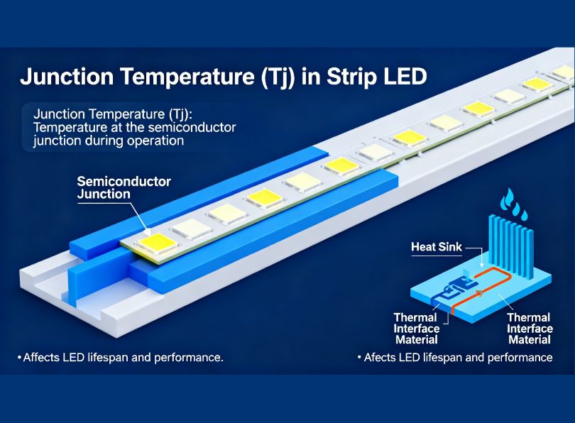
- Junction temperature (Tj): the number that decides everything
- Heat dissipation methods for led strip profiles
- Lifespan prediction: from Tj to L70 hours
- Design and optimisation of thermal systems
- Material properties and comparative data
- Market context: the LED thermal products industry
- Practical challenges and common mistakes
- Innovations and future trends
- Your questions
- Thermal management in electronic led
Why thermal management in electronic led
Let’s start with a number that should get your attention: a 10°C rise in LED junction temperature can cut the rated lifespan by roughly 50%. That figure comes from accelerated-ageing tests corroborated by multiple semiconductor manufacturers (Cree, Nichia, Osram, Lumileds) and it’s broadly consistent with the Arrhenius degradation model used across the semiconductor industry. In concrete terms, a mid-power 2835 LED that would last 50,000 hours at a junction temperature of 85°C may only reach 25,000 hours if that temperature creeps up to 95°C, and barely 10,000 hours at 115°C.
For anyone specifying LED strip systems, this means the aluminium profile is not a decorative accessory. The profile is the thermal management system. Without it, or with an undersized, one you’re effectively gambling with the longevity of the installation.
The global LED thermal products market underscores this point. Multiple analyst firms value the sector at between USD 2.5 billion and USD 5.9 billion in 2025 (the range depends on how broadly “thermal products” is defined), with compound annual growth rates of 7.5–11.6% forecast through 2033. Heat sinks—including the aluminium extrusion profiles we work with every day—remain the most widely shipped category, accounting for tens of millions of units per year globally. The LED strip fixture market alone was valued at approximately USD 9.7 billion in 2025 and is projected to approach USD 16.5 billion by 2032 at a CAGR of 7.8%.
| Source / Scope | 2024 Value (USD) | 2033 Forecast (USD) | CAGR |
|---|---|---|---|
| LED thermal products (broad scope) | ~3.9 bn | ~10.1 bn | 11.2% |
| LED thermal products (conservative scope) | ~2.5 bn | ~4.7 bn | 7.5% |
| LED strip light fixtures (global) | ~8.9 bn | ~16.5 bn | 7.8% |
| LED thermal management solutions | ~5.0 bn (est. 2025) | ~9.0 bn+ (2030) | ~10.4% |
These aren’t niche numbers. The thermal management of LED systems is now a multi-billion-dollar engineering discipline, and the choices made at the profile-design stage cascade through product reliability, warranty costs, and total cost of ownership for decades.
Heat dissipation definition and first principles
Before we dive into formulas, let’s align on what heat dissipation actually means in the context of LED strip systems. Heat dissipation is the process of transferring thermal energy from a hotter body (the LED junction) to a cooler environment (the surrounding air), through one or more intermediate materials. In an LED profile assembly, the hotter body is the tiny PN junction inside the LED chip, typically a square of gallium nitride or indium gallium nitride only a few hundred micrometres across, and the cooler environment is the ambient air surrounding the profile.
Modern mid-power LEDs convert roughly 30–50% of the electrical input energy into visible light. The remaining 50–70% becomes heat concentrated at the PN junction. In high-power packages, published research indicates that as much as 70% of input power is converted to thermal energy at the junction level. This heat must travel through several material layers to reach the outside air, and every layer introduces a thermal resistance that impedes the flow.
Conduction, convection and radiation in LED systems
Three fundamental modes of heat transfer govern the thermal performance of any LED profile assembly:
Conduction is the dominant mechanism inside the assembly. Heat flows from the LED die through the die-attach material, through the lead frame or ceramic substrate of the package, across the solder joint, into the copper traces and substrate of the PCB, through any thermal interface material, and into the aluminium body of the profile. Each of these transitions is a conduction step, and each has a quantifiable thermal resistance measured in °C/W (degrees Celsius per watt of thermal power). The thermal conductivity of the aluminium alloy used in most LED profiles is approximately 200–210 W/(m·K), which is why aluminium dominates this market: it offers an excellent balance of conductivity, weight, cost, and extrudability. For comparison, copper sits at around 385 W/(m·K), better thermally, but significantly heavier and more expensive, and standard FR-4 PCB laminate is a dismal 0.25–0.30 W/(m·K).
Convection takes over once heat reaches the outer surfaces of the aluminium profile. In a typical architectural installation, there are no fans: we rely entirely on natural convection, where warm air rises from the profile surface and is replaced by cooler air from below. The convective heat transfer coefficient for natural convection in still indoor air is typically in the range of 5–25 W/(m²·K), depending on the surface orientation, temperature differential, and geometry. This is a relatively weak mechanism, which is exactly why profile surface area is so critical: more surface area means more convective exchange.
Radiation contributes a smaller but non-negligible share of heat removal. All surfaces above absolute zero emit infrared radiation, and for an anodised aluminium profile at typical operating temperatures (40–60°C surface), radiation can account for 10–30% of total heat dissipation in still-air conditions. Anodising is important here: raw mill-finish aluminium has an emissivity of only 0.04–0.09, whereas anodised aluminium reaches 0.75–0.90. That’s a ten-fold improvement in radiative performance, and it’s one reason we almost always recommend anodised profiles for thermal-critical installations.
| Surface Finish | Emissivity (ε) | Notes |
|---|---|---|
| Polished aluminium (mill finish) | 0.04 – 0.09 | Poor radiative performance |
| Anodised aluminium (natural) | 0.75 – 0.85 | Significant improvement |
| Anodised aluminium (black) | 0.82 – 0.90 | Best radiative surface for profiles |
| Painted aluminium (white) | 0.85 – 0.95 | Good, but paint adds thermal resistance layer |
| Raw copper | 0.03 – 0.07 | Excellent conductor, poor radiator |
The thermal-resistance chain model
Engineers model the thermal path from junction to ambient as a series of resistances, analogous to electrical resistors in series. Each interface or material layer is assigned a thermal resistance value Rth (in °C/W), and the total resistance from junction to ambient is the sum:
Where:
- Rth(j-s) = junction to solder point (LED package property, from datasheet, typically 5–25 °C/W for mid-power LEDs)
- Rth(s-b) = solder joint to PCB board (depends on solder pad area, solder type, PCB copper weight)
- Rth(b-p) = PCB to aluminium profile (depends on TIM and contact quality)
- Rth(p-a) = profile to ambient air (depends on profile geometry, surface area, airflow, surface finish)
The temperature rise at the junction is then simply:
This is the fundamental equation you’ll see referenced throughout the rest of this article. Everything in LED thermal management comes back to reducing the Rth values in this chain, or reducing Pheat itself (by choosing more efficient LEDs or driving them at lower current).
Junction temperature (Tj): the number that decides everything
The junction temperature of an LED is the temperature at the semiconductor PN junction inside the chip. You can’t measure it directly with a thermocouple, the die is encapsulated under phosphor and silicone, so it must be calculated indirectly. The standard industry method starts with a solder-point temperature measurement (Ts) and then adds the temperature rise across the LED’s internal thermal resistance:
Where Ts is measured with a thermocouple placed at the LED’s solder pad (the specific location is defined in each manufacturer’s application note), Rth(j-s) comes from the datasheet, and Pheat is the thermal power dissipated.
Calculating Pheat is crucial and often done incorrectly. The thermal power is not equal to the total electrical input power. It is the input power minus the power emitted as visible light:
Where ηWPE is the wall-plug efficiency (the fraction of electrical power converted to light). For a typical modern mid-power white LED operating at rated current, ηWPE ranges from about 0.30 to 0.50. A common and conservative assumption for design purposes is ηWPE = 0.35, meaning 65% of the input power becomes heat.
How to calculate Tj in a strip led assembly
Let’s walk through the general method, step by step. We’ll use it for a concrete example in section 3.2.
Step 1: define the electrical input per LED. For a strip rated at 14.4 W/m with 60 LEDs per metre, each LED consumes 14.4 / 60 = 0.24 W.
Step 2: estimate thermal power per LED. Assuming ηWPE = 0.35, Pheat per LED = 0.24 × 0.65 = 0.156 W.
Step 3: collect thermal resistances. From the LED datasheet (e.g. a typical 2835 mid-power package), Rth(j-s) ≈ 12 °C/W. The strip’s flexible PCB adds perhaps Rth(s-b) ≈ 8 °C/W (this varies enormously depending on copper weight and dielectric). The TIM between the strip backing and the profile might contribute Rth(b-p) ≈ 2–5 °C/W. And the profile-to-ambient resistance Rth(p-a) depends on profile size, orientation, and airflow.
Step 4: determine Rth(p-a). This is usually the trickiest one. For a standard surface-mounted U-channel profile (approx. 17×8 mm cross-section) in still indoor air at 25°C, you can expect Rth(p-a) in the region of 15–35 °C/W per LED, depending on how many LEDs share the same profile length. In practice, because the LEDs are closely spaced, you should think in terms of thermal power per unit length rather than per individual LED.
Step 5: apply the formula. Sum the resistances, multiply by Pheat, add the ambient temperature. Check whether the resulting Tj is below the manufacturer’s maximum (typically 120–150 °C for mid-power LEDs) and, more importantly, below the temperature at which the desired L70 lifespan is achieved (often 85–105 °C).
Worked example: 14.4 W/m strip in a recessed profile
Let’s put real numbers in. Our scenario: a 14.4 W/m, 24 V LED strip with 60× 2835 LEDs per metre, mounted inside a standard recessed aluminium profile (23×15 mm cross-section, anodised), installed in a ceiling void with reduced airflow. Worst-case ambient: Ta = 35 °C.
| Thermal path | Resistance (°C/W) | Source |
|---|---|---|
| Junction to solder point (Rth(j-s)) — averaged across 60 LEDs in parallel | 0.20 * | LED datasheet (12 °C/W per LED, 60 in parallel) |
| Solder to PCB board (Rth(s-b)) | 0.15 | Flexible PCB with 2 oz copper |
| PCB to profile (Rth(b-p)) via 3M adhesive tape | 0.45 | Typical thermal adhesive, ~0.8 W/(m·K) |
| Profile to ambient (Rth(p-a)) — recessed mount, limited airflow | 2.8 | Measured (23×15 mm anodised profile, still air) |
| Total Rth(j-a) | 3.60 |
* When analysing per-metre, we treat the 60 LEDs in a metre length as a distributed heat source. The effective Rth(j-s) for the group is Rth(j-s) per LED / N, but the total thermal power is also N × Pheat per LED. The per-metre approach simplifies the maths considerably.
Total thermal power per metre: Pheat = 14.4 × 0.65 = 9.36 W/m.
Tj = 35 + 3.60 × 9.36
Tj = 35 + 33.7
Tj ≈ 69 °C
That’s well below the typical maximum of 120°C and comfortably within the range for achieving 50,000+ hour L70 life (which usually requires Tj < 85°C). So this combination works. But what if we remove the aluminium profile and stick the strip directly onto a plasterboard ceiling? The Rth(p-a) jumps dramatically—plasterboard is a thermal insulator with a conductivity of only 0.16–0.25 W/(m·K)—and the junction temperature can easily exceed 100°C, cutting lifespan to a fraction of what it should be.
Heat dissipation methods for led strip profiles
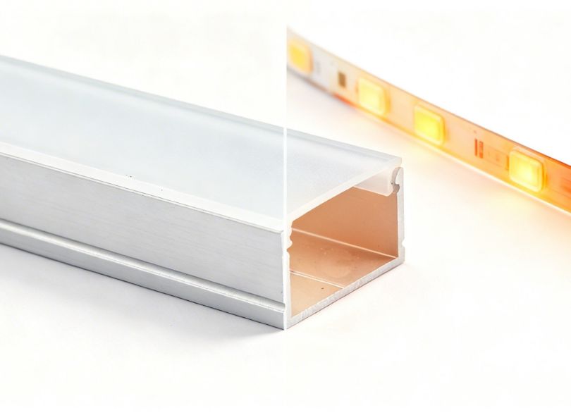
Now that we understand the thermal resistance chain, let’s look at the practical methods available to reduce each Rth in that chain. In strip-LED systems, the overwhelming majority of installations rely on passive cooling, there are no fans, no pumps, no Peltier coolers. The entire thermal management system is the combination of the PCB substrate, the thermal interface, and the aluminium extrusion. Getting these three elements right is the core of LED thermal design.
Passive cooling: aluminium extrusions and profile geometry
The aluminium profile is the primary heat sink in virtually every LED strip installation. Its job is to absorb conducted heat from the PCB and spread it over a larger surface area, from which it can be dissipated to the air by convection and radiation. The effectiveness of a profile depends on three things: mass (how much aluminium is there to absorb and spread heat), surface area (how much contact with the air), and geometry (how well the shape encourages airflow).
Our internal tests, run at 25°C ambient in a climate-controlled chamber with no forced airflow, show the following temperature reductions at the PCB solder point when the same 14.4 W/m strip is mounted on different profile types:
| Profile type | Cross-section (mm) | Ts measured (°C) | ΔT vs. no profile |
|---|---|---|---|
| No profile (strip on plasterboard) | — | 78 | — |
| Slim surface U-channel | 17 × 8 | 55 | −23 °C |
| Standard recessed U-channel | 23 × 15 | 49 | −29 °C |
| Deep surface U-channel | 30 × 20 | 44 | −34 °C |
| Wide flat profile (architectural) | 55 × 12 | 41 | −37 °C |
| Finned extrusion (industrial) | 40 × 30 (with 8 fins) | 36 | −42 °C |
The pattern is clear: more aluminium and more surface area mean lower temperatures. The finned extrusion achieves the best result, cutting the solder point temperature by 42°C compared to no profile at all. However, finned profiles cost 20–30% more than standard channels, and they’re significantly bulkier. In many architectural applications, a standard recessed channel is the sweet spot—it provides sufficient thermal performance for strips up to about 14–15 W/m in normal indoor conditions, while maintaining a slim aesthetic.
For higher-power strips (19.2 W/m and above), or for installations in confined spaces with elevated ambient temperatures, we generally recommend moving up to a deep-channel or finned profile. The incremental cost is modest, and the lifespan improvement can be substantial, potentially extending LED service life by 30–50% according to accelerated ageing projections.
Thermal interface materials (TIMs)
The interface between the back of the LED strip PCB and the aluminium profile is a critical bottleneck. If the strip is simply placed in the channel with no thermal coupling, relying on the air gap between the flex PCB and the aluminium, the Rth(b-p) can be very high (air has a thermal conductivity of only 0.026 W/(m·K)). Even microscopic air gaps drastically impede heat transfer.
Common thermal interface options for LED strip installations include:
| TIM type | Thermal conductivity (W/(m·K)) | Typical thickness (μm) | Pros | Cons |
|---|---|---|---|---|
| 3M VHB acrylic tape (standard) | 0.15 – 0.25 | 500 – 1100 | Easy to apply, strong bond | Poor thermal performance, thick |
| Thermally conductive adhesive tape | 0.8 – 1.5 | 100 – 250 | Good balance of bonding and thermal transfer | Costs more than standard tape |
| Thermal grease / paste | 1.0 – 5.0 | 25 – 75 | Excellent thermal transfer, fills micro-voids | Messy, no mechanical bond, pump-out over time |
| Thermal pad (silicone-based) | 1.5 – 6.0 | 250 – 1000 | Compressible, conforms to surfaces | Higher Rth due to thickness |
| Phase-change material (PCM) | 3.0 – 8.0 | 25 – 100 | Melts at operating temp, fills all gaps | Expensive, requires mechanical clamping |
The single biggest thermal mistake we see in the field is installers relying on the strip’s standard 3M self-adhesive backing as the sole thermal interface. That tape is designed for mechanical adhesion, not thermal conduction. Its thermal conductivity is typically 0.15–0.25 W/(m·K)—barely better than air—and at 0.5–1.1 mm thick, it introduces a substantial thermal resistance. Switching to a dedicated thermally conductive tape (0.8–1.5 W/(m·K)) can reduce Rth(b-p) by 60–75%, which translates directly to a lower junction temperature.
PCB substrate selection: FR-4 vs. MCPCB vs. flexible
The circuit board on which the LEDs are mounted is another major thermal player. Most LED strips use a flexible PCB (FPCB) based on polyimide film with copper traces, while rigid LED modules often use metal-core PCBs (MCPCBs). The thermal performance difference is significant:
| Substrate type | Thermal conductivity (W/(m·K)) | Typical use |
|---|---|---|
| Standard FR-4 | 0.25 – 0.30 | Low-power LED modules, general electronics |
| Flexible PCB (polyimide) | 0.20 – 0.35 | LED strips (most common) |
| Aluminium-core MCPCB (1.0 W dielectric) | 1.0 | Mid-power rigid LED modules |
| Aluminium-core MCPCB (2.0 W dielectric) | 2.0 | High-power LED modules |
| Aluminium-core MCPCB (3.0+ W dielectric) | 3.0+ | High-power, thermally critical applications |
| Copper-core MCPCB | 380+ | Ultra-high-power, cost-no-object |
| Ceramic substrate (Al2O3) | 24 – 30 | High-reliability, harsh-environment modules |
The take-away here is that a flexible LED strip on a polyimide substrate is inherently at a thermal disadvantage compared to a rigid module on an MCPCB. This is not a flaw it’s a trade-off: flexibility and ease of installation versus thermal conductivity. The aluminium profile compensates for this by acting as the external heat spreader that the FPCB alone cannot provide. For high-power flexible strips (19.2 W/m and above), ensuring excellent thermal contact between the FPCB and the profile is even more important, and we strongly recommend thermally conductive tape or mechanical clamping with thermal paste.
Lifespan prediction: from Tj to L70 hours
LED manufacturers specify lifespan using the L70 metric: the number of operating hours after which the LED’s light output has depreciated to 70% of its initial value. This is the industry-standard failure criterion defined by IES LM-80 and TM-21. The L70 figure is always tied to a specific junction temperature—typically Tj = 85 °C or Tj = 105 °C. Running the LED at a different Tj than the test condition changes the lifespan dramatically.
The Arrhenius model and the “10°C rule”
The relationship between temperature and degradation rate in semiconductors follows the Arrhenius equation, which in simplified form gives:
This is the famous “10-degree rule”: for every 10°C reduction in junction temperature, the LED lifespan approximately doubles, and conversely, every 10°C increase halves it. The exponent of 10 is an approximation; the actual value depends on the activation energy of the specific degradation mechanism and varies somewhat between LED chemistries. But for engineering design purposes, the 10°C rule is widely accepted and used by major manufacturers in their lifespan projection tools.
Lifespan data table by junction temperature
The following table illustrates the projected L70 lifespan for a typical high-quality mid-power white LED (e.g. 2835 or 3030 package class) at various junction temperatures, using manufacturer data and the Arrhenius extrapolation:
| Tj (°C) | Estimated L70 (hours) | Equivalent years (12 h/day) | Notes |
|---|---|---|---|
| 65 | > 100,000 | > 22 | Excellent — premium installations |
| 75 | ~80,000 | ~18 | Very good — well-designed profile system |
| 85 | ~50,000 | ~11 | Standard test condition — typical rating |
| 95 | ~25,000 | ~5.7 | Marginal — consider larger profile |
| 105 | ~12,500 | ~2.9 | Poor — high-temperature test condition |
| 115 | ~6,000 | ~1.4 | Failure zone — unacceptable for most applications |
| 125 | ~3,000 | ~0.7 | Rapid degradation — near absolute maximum rating |
These numbers should give pause to anyone who considers thermal management optional. The difference between a well-cooled LED running at 75°C junction temperature and a poorly managed one running at 105°C is the difference between an 18-year installation and a 3-year one. In a commercial fit-out where labour costs for re-lamping can be several times the cost of the LED strip itself, that lifespan difference represents a massive total-cost-of-ownership gap.
Design and optimisation of thermal systems
This section is where theory meets practice. We’ll discuss the design decisions that have the greatest impact on the thermal performance of an led profile system, based on our experience developing and testing aluminium extrusions for the European lighting market.
Profile geometry: flat channel vs. finned extrusion
The cross-sectional shape of the aluminium profile determines both its thermal mass and its convective surface area. Surface area is king for natural convection. A flat-bottomed U-channel has a relatively limited surface area, while a finned extrusion can offer 3–5× more air-contact surface for the same base width.
However, fin design is not as simple as “more fins = better cooling.” Research on heat sink fin optimisation shows that if fins are spaced too closely, they restrict airflow between them, and convection stalls. The optimal fin spacing for natural convection depends on the Rayleigh number and the fin height, but as a practical guideline for LED profile-sized extrusions, a minimum fin spacing of 4–6 mm is needed to maintain effective airflow. Fins that are too thin (below about 1 mm) can also be counterproductive because they don’t conduct heat effectively to their tips.
For most architectural LED strip applications, we find that the best compromise is a wide, flat-bottomed profile with moderate wall thickness (1.5–2.5 mm) rather than a complex finned geometry. The wide flat base spreads heat laterally, increasing the effective surface area without the bulk of fins. For industrial or high-power applications (continuous runs at 19–25 W/m or higher), finned profiles become the right choice.
Mounting orientation and airflow considerations
Mounting orientation has a surprisingly large effect on natural-convection performance. The fundamental rule: a horizontal profile with the heated surface facing upward dissipates heat more efficiently than one facing downward, because hot air rises naturally from the top surface. In tests, the difference can be 10–20% in thermal resistance.
This matters practically. A ceiling-recessed profile where the LED strip faces downward (to illuminate the room below) has the aluminium body above the LEDs, with the outer surface facing into the ceiling void. If that void is poorly ventilated, common in insulated ceilings, the warm air has nowhere to go, and the profile’s convective performance degrades significantly. In such installations, we recommend either specifying a deeper profile (to provide more thermal mass), ensuring the ceiling void has some ventilation path, or de-rating the strip to a lower wattage.
Suspended profiles (hanging from cables in open air) actually have good thermal performance because air can circulate freely around all surfaces. The trade-off is that the profile loses direct conductive contact with a mounting surface, so it has to dissipate all heat through its own surfaces alone. For moderate power levels (up to about 14 W/m), this works well. For higher power, the suspended profile needs to be larger to compensate.
Thermal simulation: when to use FEA
For standard applications with well-characterised components, the hand-calculation method we described is usually sufficient. But there are situations where finite element analysis (FEA) thermal simulation is worthwhile:
- custom profile geometries where empirical Rth data doesn’t exist;
- high-power installations (> 20 W/m) where margins are thin;
- enclosed or semi-enclosed installations (recessed into insulated ceilings, inside furniture, behind glass);
- large-scale projects where a thermal miscalculation would be costly;
- products intended for certification (UL, CE, ENEC) where documented thermal evidence is required.
Modern FEA tools like ANSYS Icepak, Siemens Simcenter Flotherm, or even the free OpenFOAM with conjugate heat transfer can model the entire assembly (LED packages, PCB, TIM, aluminium profile, diffuser, and surrounding air) and predict temperature distributions with good accuracy (typically within ±5°C of measured values when boundary conditions are well defined).
Material properties and comparative data
Selecting the right materials at every layer of the thermal chain is fundamental. The table below consolidates the key thermal properties of materials commonly encountered in LED profile systems. We reference this data regularly when advising customers on system design.
| Material | Thermal conductivity (W/(m·K)) | Density (kg/m³) | Typical application in LED systems |
|---|---|---|---|
| Copper (pure) | 385 – 401 | 8,960 | PCB traces, high-end heat spreaders |
| Aluminium 6063-T5 | 200 – 210 | 2,700 | Extrusion profiles (most common alloy) |
| Aluminium 6061-T6 | 167 – 175 | 2,700 | Machined heat sinks, structural profiles |
| Alumina ceramic (Al2O3) | 24 – 30 | 3,900 | High-reliability LED substrates |
| Solder (SAC305) | 58 – 62 | 7,400 | LED package attachment |
| Silicone encapsulant | 0.15 – 0.30 | 1,100 | LED phosphor encapsulation |
| Polyimide (Kapton, FPCB base) | 0.12 – 0.35 | 1,420 | Flexible LED strip substrate |
| FR-4 (glass-reinforced epoxy) | 0.25 – 0.30 | 1,850 | Rigid PCB substrate (poor thermal choice) |
| Polycarbonate (diffuser) | 0.19 – 0.22 | 1,200 | Profile diffuser/cover (thermal insulator) |
| PMMA / Acrylic (diffuser) | 0.17 – 0.20 | 1,180 | Alternate diffuser material |
| Steel (mild) | 50 – 55 | 7,850 | Occasionally used for brackets (poor choice as heat sink) |
| Air (still, at 25 °C) | 0.026 | 1.18 | The medium we dissipate into |
| Plasterboard / Drywall | 0.16 – 0.25 | 800 | Mounting surface (thermal insulator) |
The contrast between aluminium (200+ W/(m·K)) and the substrate materials (0.12–0.35 W/(m·K)) should make it visually clear why the profile is so critical. The profile isn’t merely a housing, it’s the thermal highway that bridges the gap between the LED’s tiny, concentrated heat source and the large volume of ambient air that will ultimately absorb that energy.
Market context: the led thermal products industry
Understanding the market landscape helps contextualise why thermal management in LED systems is receiving increasing attention. The LED lighting industry has matured to the point where product differentiation increasingly comes down to lifespan, reliability, and total cost of ownership, all of which are directly influenced by thermal design.
The global LED aluminium profile market was valued in the tens of billions of dollars in 2025 as part of the broader lighting fixtures market, with growth projections to nearly USD 61.5 billion by 2025 for the LED aluminium profile segment specifically (including all applications), with a CAGR of 8.1% through 2030. The thermal products sub-segment, heat sinks, MCPCBs, thermal pads, fan sinks, thermal clad boards, is growing even faster, driven by the trend towards higher-power LED systems that demand more aggressive thermal solutions.
| Finding | Percentage | Implication |
|---|---|---|
| Manufacturers stating thermal management tech will define future market growth | 80% | Thermal design is becoming a key competitive differentiator |
| Industrial facility managers identifying smart lighting integration as a top trend | 64% | Smart systems need reliable thermal data for predictive maintenance |
| High-power LEDs globally using some form of thermal management solution (2024) | > 80% | Thermal management is now standard, not optional |
| Commercial developers expecting wireless controls and predictive maintenance by 2030 | 48% | Thermal monitoring will integrate into building management systems |
| European facility managers citing regulatory frameworks as driver for LED adoption | 72% | Regulations increasingly reference thermal performance standards |
For product designers and engineers reading this, the trend is clear: the days of treating the aluminium profile as a commodity mounting channel are over. Increasingly, the profile is a precision thermal component that needs to be specified, tested, and validated as part of the luminaire design, not bolted on as an afterthought.
Practical challenges and common mistakes
Over fifteen years of working with LED profile installations across Europe, our team has catalogued a depressingly long list of thermal design errors. Here are the ones we see most frequently, along with guidance on how to avoid them.
Relying on standard adhesive tape as a thermal interface
We’ve mentioned this already, but it bears repeating. Standard 3M VHB or generic double-sided tape is a mechanical bonding product, not a thermal interface material. Its thermal conductivity (0.15–0.25 W/(m·K)) is barely better than air. In an informal test we ran in 2024, switching from standard tape to a 1.0 W/(m·K) thermally conductive tape on a 14.4 W/m strip reduced the solder-point temperature by 8°C, a difference that, per the Arrhenius model, equates to roughly 40–50% more operating life.
Installing strips in enclosed spaces without thermal de-rating
A recessed profile in an insulated ceiling, a strip inside a sealed display case, a linear light behind a closed glass panel, these are all environments where the ambient temperature around the profile is significantly higher than room temperature. We’ve measured ceiling voids at 40–50°C in summer, which is 15–25°C above the 25°C typically assumed in product datasheets. If the strip is running at its full rated power in these conditions, the junction temperature can easily blow past 100°C.
The fix is simple: de-rate the strip. Either reduce the drive current (dimming to 70–80% of maximum), or specify a strip with fewer watts per metre for enclosed installations. Alternatively, upsize the profile to one with a lower Rth(p-a).
Ignoring the polycarbonate diffuser’s insulating effect
The diffuser (or cover) that clips onto the top of the profile is a thermal insulator. Polycarbonate has a thermal conductivity of only 0.19–0.22 W/(m·K). If the diffuser traps a layer of warm air above the LEDs, it reduces convective cooling from the top surface of the profile. In our measurements, profiles with the diffuser installed run approximately 3–6°C warmer at the solder point than the same profile without a cover, depending on the profile geometry and how well the ends are ventilated. For thermally critical installations, consider leaving the profile ends uncapped to allow some through-airflow, or specify a profile with ventilation slots.
Choosing the wrong profile for the wattage
This is perhaps the most common error of all, and it usually happens because the profile is selected for its aesthetic dimensions rather than its thermal capacity. A slim 12×7 mm surface profile might look elegant, but it simply doesn’t have enough thermal mass or surface area to handle a 19.2 W/m strip in a confined space. We always recommend that specifiers check the profile manufacturer’s thermal data (maximum recommended strip wattage per profile type, ideally with test temperature data) before committing to a product. If this data isn’t available, treat it as a red flag.
Failing to account for ambient temperature variation
LED installations are not laboratory environments. The ambient temperature varies with season, time of day, building HVAC status, and location within the building. Always design for the worst-case ambient temperature the installation will face, not the average. For indoor European installations, we typically use Ta = 35°C as a design value for open spaces and Ta = 40–45°C for ceiling voids, display cases, and other enclosed locations. For outdoor installations in southern Europe or the Middle East, Ta = 45–50°C may be appropriate.
Innovations and future trends
The LED thermal management industry doesn’t stop there. It’s worth keeping an eye on several emerging technologies and trends. Let’s see which ones.
Advanced thermal interface materials
Next-generation TIMs incorporating graphene, boron nitride nanosheets, or carbon nanotubes are achieving thermal conductivities in the range of 10–50 W/(m·K), an order of magnitude better than current silicone-based pads. While these are still primarily in the research and early-adoption phase, they’re beginning to appear in premium LED products. As costs come down, they could largely eliminate the TIM as a thermal bottleneck in profile systems.
Phase-change materials for thermal buffering
Phase-change materials (PCMs) absorb large amounts of heat during melting (latent heat) at a fixed temperature. Incorporating a PCM layer into an LED profile could buffer thermal transients, for example, absorbing the initial heat surge when a high-power strip is switched on, and releasing it slowly after switch-off. This approach is being explored for applications with intermittent high-power operation, such as retail display lighting with scheduled on/off cycles.
Smart thermal monitoring
The integration of temperature sensors (NTC thermistors or digital sensors) into LED profiles and driver systems is enabling real-time thermal monitoring. Combined with intelligent drivers, this allows automatic thermal throttling: if the measured temperature exceeds a threshold, the driver reduces current to bring the junction temperature back to safe levels. This is particularly valuable in installations where ambient conditions are variable or unpredictable. Several LED driver manufacturers now offer this feature, and it’s increasingly appearing in specification documents for commercial projects.
Miniaturised high efficiency profiles
Market trends indicate growing demand for ultra-slim profiles (under 10 mm depth) that can integrate seamlessly into modern minimal interiors. Achieving adequate thermal performance in these small form factors requires innovations in extrusion geometry, thinner walls with optimised internal fin structures, or composite profiles combining aluminium with thermally conductive polymers. The challenge is substantial, because physics doesn’t negotiate: less material means less thermal mass and less surface area. But clever design can partially offset this through improved airflow paths and higher-emissivity surface treatments.
Sustainability and recyclability
Aluminium is already one of the most recyclable materials in common use (recycling aluminium requires only about 5% of the energy needed to produce primary aluminium). As sustainability regulations tighten in Europe and globally, the full recyclability of aluminium LED profiles is becoming a positive differentiator. Industry forecasts suggest that recyclable aluminium and eco-friendly production processes will drive approximately 20% of LED profile market growth by 2030, according to recent market analysis.
Your questions
How is heat dissipation calculated in an LED strip system?
Heat dissipation is calculated using the thermal resistance chain model: Tj = Ta + (Rth(j-s) + Rth(s-b) + Rth(b-p) + Rth(p-a)) × Pheat. First, determine the thermal power by subtracting the optical power from the electrical input: Pheat = Pelectrical × (1 − ηWPE). Then, sum the thermal resistances from the LED junction to the ambient air, and multiply by the thermal power. Add the ambient temperature to get the predicted junction temperature.
How can we reduce heat in LED strip installations?
The most effective strategies are: use an appropriately sized aluminium extrusion profile; select a thermally conductive interface material (not standard adhesive tape); choose LED strips with high wall-plug efficiency; drive the LEDs below their maximum rated current; ensure adequate airflow around the profile; avoid enclosed mounting without thermal de-rating; and consider wider or finned profiles for high-power strips.
Is heat dissipation good or bad for LEDs?
Heat dissipation is unequivocally good—in fact, it’s essential. The heat generated at the LED junction must be dissipated to maintain acceptable junction temperatures. Without adequate dissipation, Tj rises, causing accelerated lumen depreciation, colour shift, and reduced lifespan. Effective thermal management (heat dissipation) is what enables LEDs to achieve their rated 50,000+ hour lifespans.
What are the three types of heat dissipation?
The three fundamental heat transfer mechanisms are conduction (heat flow through solid materials), convection (heat transfer to a moving fluid, typically air), and radiation (heat emission as electromagnetic waves). In an LED profile system, conduction moves heat from the junction to the profile surface, convection and radiation together carry it from the profile surface to the surrounding environment.
What is poor heat dissipation, and what are its consequences?
Poor heat dissipation means the thermal path from the LED junction to the environment has excessive thermal resistance, causing the junction temperature to rise above safe operating levels. Consequences include: accelerated lumen depreciation (the LEDs get dimmer faster), colour-temperature shift (the light becomes warmer/yellower), phosphor degradation, solder-joint fatigue, driver component stress, and ultimately premature failure. A 10°C rise in Tj can halve the rated lifespan.
Why is thermal management important in LED profiles specifically?
LED strips mounted in profiles operate as continuous linear heat sources, often in enclosed or semi-enclosed geometries. The combination of distributed thermal load, limited airflow (especially in recessed profiles), and compact cross-sections makes thermal management more challenging than in many other LED applications. The aluminium profile is both the enclosure and the heat sink, so its design directly determines the thermal performance and longevity of the entire system.
What does a thermal management system do in LED lighting?
A thermal management system maintains the LED junction temperature within safe operating limits by providing a low-resistance thermal path from the junction to the ambient environment. In profile-based LED systems, this system consists of the LED package’s internal thermal path, the PCB substrate, the thermal interface material, and the aluminium extrusion acting as a passive heat sink. Together, these elements ensure that the heat generated at the junction is conducted, spread, and ultimately dissipated to the surrounding air.
How do you determine the right profile for a given LED strip wattage?
Start by calculating the thermal power: Pheat = Pelectrical × (1 − ηWPE). Then, define your target maximum Tj (we recommend ≤ 85°C for long-life installations) and your worst-case Ta. Calculate the required total Rth(j-a) = (Tj,max − Ta) / Pheat. Subtract the known Rth values for the LED package, PCB, and TIM to find the maximum allowable Rth(p-a) for the profile. Then select a profile whose Rth(p-a) (from the manufacturer’s thermal data) meets or beats that requirement.
Thermal management in electronic led
Thermal management in LED profile systems is the practical foundation upon which the product’s lifespan, reliability, and long-term value are built. The physics are well understood, the formulas are simple, and the data are available. The challenge is the discipline to apply that knowledge consistently throughout every phase of design, specification, and installation.
We have seen that:
The junction temperature Tj is the most important parameter for LED longevity. Every 10°C reduction in Tj approximately doubles the lifespan. Design your thermal system to keep Tj below 85°C under worst-case conditions for a rated lifespan of over 50,000 hours.
The thermal resistance chain is your analytical framework. Tj = Ta + Rth(j-a) × Pheat. Each layer of the chain—LED package, solder joint, PCB, TIM, profile, and ambient—contributes to a resistance you can quantify and optimize.
The aluminum profile is the dominant thermal component. It provides the thermal mass and surface area needed to bridge the gap between the heat concentrated at the LED junction and the diluted heat absorption capacity of the surrounding air.
Material choice is important for every interface. Switching from standard adhesive tape to a thermally conductive TIM can reduce the junction temperature by 5-10°C.
Choosing the right PCB substrate, profile alloy, and surface finish contribute to the overall thermal balance.