Every year, millions of linear metres of aluminium led profiles are installed across Europe in homes, offices, retail spaces, hospitality venues, healthcare facilities and industrial environments. The global led profile market (valued at over USD 1.8 billion in 2024 and projected to exceed USD 3.2 billion by 2030 according to industry analysts) continues to grow at a compound annual rate of roughly 9.5 %. That growth is driven by a simple fact: led strip lighting housed inside an aluminium extrusion delivers the most elegant, durable and thermally efficient form of architectural illumination available today. Yet despite this enormous adoption, a surprising number of installations fail prematurely or look unprofessional because the person who cut, joined and mounted the profile on site lacked a clear, methodical procedure to follow.
This guide exists to close that gap.Whether you are an electrician wiring a complete lighting circuit, a plasterboard contractor embedding trimless channels into a ceiling, or a fit-out installer surface-mounting slim profiles under kitchen cabinets, the ability to install aluminium led profiles correctly is now an essential trade skill. A poorly cut profile leaves visible burrs that scratch diffusers, a badly joined profile creates dark spots and thermal weak points and a carelessly mounted profile bows away from the surface, producing uneven shadow lines that no amount of sealant can hide. Every one of these defects is avoidable when you understand the materials, choose the right tools, and follow a logical sequence of operations from the first measurement to the final end cap.
This field guide is written for tradespeople who work on real construction sites, not laboratory conditions. It assumes you already know how to strip a wire and drive a screw, and it respects your time by organising every section around the practical questions you will face when you install aluminium led profiles on a live project. We will walk through the complete process: surveying and planning the run, selecting the correct profile for each surface type, cutting aluminium to length cleanly, joining sections for continuous light lines, fixing profiles to plasterboard, concrete, timber and metal substrates, trimming and connecting led strips with correct polarity, choosing the right diffuser for the desired light quality, and finishing with end caps that protect the electronics and give the installation a polished, professional appearance.
In this article…
- Why aluminium led profiles matter — The case for proper installation
- Planning and surveying before you install aluminium led profiles
- Comprehensive tool list — What you need on site
- How to cut aluminium led profiles — Complete method
- How to cut led strips to match profile lengths
- How to join aluminium led profiles — Mechanical connections
- Connecting led strips — Electrical wiring inside the profile
- How to install aluminium led profiles on different surfaces
- Selecting the right profile for the surface
- Joining profiles for continuous runs — Detailed procedures
- On-site installation techniques
- Diffuser selection and light quality
- Thermal management — Protecting your leds
- Voltage drop, power supply sizing and cable runs
- Dimming and control wiring inside profiles
- Waterproofing and outdoor installations
- Quality control, testing and commissioning
- Troubleshooting common installation problems
- Installation case studies and project examples
- Maintenance, cleaning and long-term care
- Codes, standards and regulatory considerations
- Frequently asked questions (FAQ)
- Mastering the art of led profile installation
Why aluminium led profiles matter — The case for proper installation
Before you pick up a saw or reach for a mounting clip, it is worth pausing to understand exactly why the aluminium extrusion matters so much in a modern led lighting system. When you install aluminium led profiles correctly, you are not simply adding a decorative trim around a strip of leds. You are providing a precision-engineered housing that serves three critical functions simultaneously: thermal management, optical control and mechanical protection. Each of these functions directly affects the performance, lifespan and appearance of the finished lighting installation. Getting any one of them wrong (through a sloppy cut, a loose joint or an inappropriate profile choice) can degrade the entire system. The following sub-sections explain each function in detail so you can make informed decisions at every step of the installation process.
Thermal management and led longevity
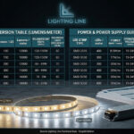
Light-emitting diodes produce light very efficiently compared to incandescent or halogen sources, but they still convert a significant portion of the electrical energy they consume into heat. A typical mid-power led package operates at a junction temperature that must stay below 80–85 °C to maintain its rated lumen output and achieve its stated lifespan, commonly 50,000 hours or more at L70 (the point at which output drops to 70 % of initial lumens). Without an adequate heat sink, junction temperatures can climb past 100 °C within minutes, accelerating lumen depreciation, shifting colour temperature and ultimately causing premature failure.
When you install aluminium led profiles, the aluminium extrusion acts as an extended heat sink. Aluminium has a thermal conductivity of approximately 205 W/m·K, which means it draws heat away from the led junction and disperses it across the full length and surface area of the profile. The larger the cross-section of the profile, the greater its ability to dissipate heat. A slim surface-mount profile like the LLP-SL13-02 (only 5 mm high) is perfectly adequate for low-power strips of up to roughly 10 W/m. But for high-output strips running at 20 W/m or more, you need a profile with a substantially larger thermal mass: for example, the LLP-CL02-07 with its generous 50 × 75 mm cross-section. This is not optional: it is a fundamental engineering requirement that directly determines how long the leds will last in service.
The thermal bond between the led strip and the profile is equally important. Most led strips feature a 3M adhesive backing that provides both mechanical adhesion and a degree of thermal coupling. However, the thermal conductivity of adhesive tape is far lower than that of aluminium, so for high-power applications many professionals add a thin layer of thermal compound (thermal paste or thermal adhesive tape rated above 1.0 W/m·K) between the strip and the profile base. This can reduce junction temperature by 5–10 °C, which translates directly into longer led life.
Optical control and light quality
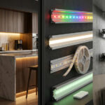
An led strip mounted to a bare surface with no profile or diffuser produces harsh, point-source light with individual led chips clearly visible. This “dotting” effect is unacceptable in virtually every architectural application. When you install aluminium led profiles and fit a diffuser cover, you transform that row of discrete point sources into a smooth, continuous line of light. The diffuser scatters and blends the light from adjacent leds so the eye perceives a uniform glow rather than a string of bright dots.
The degree of diffusion and the corresponding trade-off in light transmission, depends on the type of diffuser you choose. LightingLine offers diffusers in several variants: transparent (FK) covers retain approximately 74 % of the original lumen output but offer minimal dot-hiding, satin (FS) covers provide a good balance between output retention (roughly 52–56 %) and visual uniformity and opal or opaque (FM) covers deliver the smoothest, most dot-free light at the cost of retaining only about 52–56 % of flux. For applications requiring a controlled beam angle rather than broad diffusion (for instance, accent lighting on a shelf or display) lensed diffusers such as the LLD-06-XK1-L1 can narrow the output to a 60° cone. We will explore diffuser selection in full detail in Section 12, but the key point for now is this: the profile-and-diffuser assembly is not a cosmetic afterthought — it is the optical engine that shapes the quality of light your client sees.
Mechanical protection and code compliance
led strips are flexible circuit boards. They are fragile. Left exposed, they are vulnerable to physical damage, dust ingress, moisture, UV degradation of the phosphor coating, and accidental contact by building occupants. When you install aluminium led profiles, you enclose the strip inside a rigid, durable housing that shields it from all of these hazards. End caps seal the open ends of the profile, preventing dust and insects from entering the channel. The diffuser protects the led surface from fingerprints, cleaning agents and minor impacts.
From a regulatory standpoint, enclosing led strips inside profiles also helps to satisfy electrical safety requirements. In many European jurisdictions, exposed live conductors at extra-low voltage (SELV circuits operating at 12 V, 24 V or 48 V DC) must be protected against accidental contact, especially in accessible locations. An aluminium profile with a snap-in diffuser effectively provides this protection, giving the installation a more robust compliance position during inspection. While local regulations vary and you should always consult your national wiring rules (for example, BS 7671 in the United Kingdom, NF C 15-100 in France, or CEI 64-8 in Italy), the general principle holds: a properly profiled led strip installation is inherently safer and more code-compliant than a bare-strip installation.
Market data: growth of led profile installations
To put the importance of professional installation skills in context, consider the following market data. The numbers reinforce why learning to install aluminium led profiles is an investment in your career and your business.
| Metric | Value | Source / Year |
|---|---|---|
| Global led linear lighting market value | USD 1.8 billion | Industry reports, 2024 |
| Projected market value by 2030 | USD 3.2 billion | Industry forecast, 2024 |
| Compound annual growth rate (CAGR) | ~9.5 % | 2024–2030 forecast |
| Europe’s share of global led profile demand | ~34 % | Trade estimates, 2024 |
| Percentage of architects specifying led profiles in new-build projects | 72 % | Architectural lighting survey, 2023 |
| Average led lifespan with proper thermal management (L70) | 50,000+ hours | Manufacturer datasheets |
| Average led lifespan without heat sink | 15,000–25,000 hours | Thermal studies, 2022 |
| Percentage of installation callbacks related to poor cutting or joining | ~28 % | Installer trade survey, 2023 |
The final row of that table is the most important for anyone who already works on site: nearly three out of every ten callbacks on led profile jobs are caused by cutting or joining errors. That is time and money lost on repeat visits that could have been avoided with the correct technique the first time. Learning to install aluminium led profiles properly is not just about craftsmanship, it is about profitability.
Planning and surveying before you install aluminium led profiles
The most experienced installers will tell you the same thing: the quality of any led profile installation is determined before the first cut is made. Planning and surveying are where you identify obstacles, confirm dimensions, choose the right products and calculate material quantities. Rushing this stage costs more time later than it saves now. This section provides a structured approach to the pre-installation phase so that when you do start to install aluminium led profiles on site, every piece of material is on hand, every measurement is confirmed and every potential problem has been anticipated.
Site survey checklist
A thorough site survey is the foundation of a successful installation. Before ordering materials, visit the site and work through the following checklist systematically. Document everything with photographs and notes, you will refer back to them when preparing your material take-off and work plan.
Substrate identification: walk the full length of every proposed profile run and record the surface material: plasterboard on timber studs, plasterboard on metal studs, solid masonry, concrete soffit, timber joists, MDF cabinetry, metal suspended ceiling grid, or something else. Each substrate demands a different fixing method, and the profile type you specify must be compatible with the mounting approach. For instance, if the architect has specified a trimless plasterboard detail, you need a profile from the LLP-DW series that is specifically designed to be plastered over. If the surface is a finished ceiling where no recess exists, a surface-mount LL-SL series profile is the appropriate choice.
Dimensional survey: measure every run length to the nearest millimetre. Record the distances between any corners, obstacles (downlights, sprinkler heads, HVAC diffusers, structural beams) and the planned start and end points of each profile run. Note any alcoves, bulkheads or changes in level. Measure the available depth for recessed profiles, many trimless channels require a minimum void of 30–60 mm behind the plasterboard layer, and if that depth is not available the profile will not fit.
Electrical infrastructure: identify where the mains power feeds are located or can be brought to. Decide where the led drivers (power supplies) will be mounted, ideally in a ventilated, accessible location such as above a false ceiling, inside a service cupboard or within a dedicated electrical enclosure. Measure the cable run distances from driver to the first point of connection on the led strip, because these distances affect voltage drop calculations (covered in Section 14). Note any existing dimming infrastructure (DALI bus wires, 0–10 V control cables, or smart-home hubs) that the led system needs to integrate with.
Environmental conditions: is the installation indoors or outdoors? Is the space air-conditioned or does it experience temperature extremes? Is there exposure to moisture (bathroom, kitchen, pool area, exterior soffit)? The answers determine whether you need standard profiles or sealed/gasketed versions, and whether the led strip must carry an IP65 or IP67 rating.
Access and logistics: can you get a mitre saw stand into the space, or will all cutting happen in a workshop or corridor? Are there scaffolds, lifts or ladders already on site? What is the maximum length of profile you can transport into the space without damage, this affects whether you order 2-metre or 3-metre bars, and how many joints you will need.
Measuring for profiles: techniques and tolerances
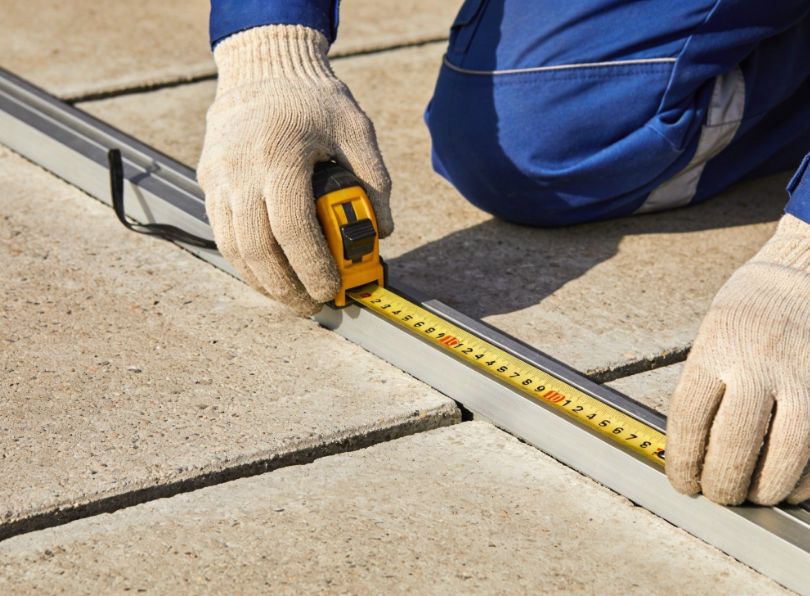
Accurate measurement is essential when you install aluminium led profiles because even a 2–3 mm error becomes visible on a finished installation. The gap at the end of a surface-mount profile that falls short of the wall is impossible to hide. A profile that is 3 mm too long will not sit flat because it is being compressed against both walls. Measure twice, cut once is the oldest rule in the trades, and it has never been more relevant than when working with aluminium extrusions where every millimetre shows.
Use a steel tape measure, not a fabric tape. Steel tapes are accurate to ±0.5 mm over 3 metres, which is well within the tolerance required for profile work. Lock the tape firmly and take your reading at eye level to avoid parallax. For long runs, have a second person hold the far end of the tape, a sagging tape introduces error. If the run exceeds the comfortable reach of a single tape measure, measure in sections and mark reference points on the surface with a fine pencil or low-tack masking tape.
Account for end caps: most end caps add 1–2 mm to the total length of the profile assembly. If your profile run must fit precisely between two walls, deduct the combined thickness of both end caps from your measured wall-to-wall distance to arrive at the correct cut length for the aluminium. This is a small detail but one that frequently catches first-time installers.
Account for joints: if your run requires a linear joint to connect two sections, the joint connector itself is internal (it slides inside the profile) so it does not add length. However, you should allow a gap of approximately 0.5 mm between the butting ends of the two profiles to ensure the joint connector can draw them tightly together without any overlap. When measuring a run that includes a corner joint, remember that the joint has a defined geometry (90°, 120°, etc.) and the profiles must be cut to allow for the distance occupied by the joint body.
Planning power entry points and driver locations
The location where the power cable enters the profile affects both the aesthetics and the electrical performance of the installation. Power should ideally be fed from one end of the profile, with the cable passing through a pre-drilled hole in the end cap. Many LightingLine end caps feature a pre-formed knockout or drilled hole specifically for clean cable entry. If the run is longer than the maximum recommended single-feed length for the led strip (typically 5 metres for 12 V strips or 10 metres for 24 V strips), you will need to plan for dual-end feed or centre feed to avoid visible brightness differences caused by voltage drop. We will examine voltage drop calculations in detail in Section 14.
The driver itself should be mounted in a location that is accessible for maintenance and replacement, ventilated to prevent overheating, and as close as practical to the led strip to minimise cable losses. In residential installations, drivers are commonly placed inside switch cupboards, in ceiling voids or within furniture carcases. In commercial installations, they are often mounted in dedicated lighting control panels or trunking above false ceilings.
Material take-off: calculating quantities
Once you have completed your site survey and measurements, you can prepare a material take-off. A methodical take-off prevents costly return visits to the supplier and ensures you have every component on site before you start to install aluminium led profiles. The following table provides a framework for a typical take-off, adapt it to your specific project.
| Item | How to calculate | Allowance |
|---|---|---|
| Aluminium profile (metres) | Total run length from measurements | Add 5 % for cutting waste |
| Diffuser cover (metres) | Same as profile length | Add 5 % for cutting waste |
| led strip (metres) | Same as total profile length | Add 10 %, strip can only be cut at designated points, so you may lose short sections |
| Linear joints | One per straight joint between profile sections | Order 1–2 spares |
| Angular joints (90° or 120°) | One per corner | Order 1 spare per type |
| End caps (pairs) | One pair per continuous run | Order 1 spare pair |
| Mounting clips or springs | One every 300–500 mm of run length | Order 10 % extra |
| led driver(s) | Total wattage of led strips ÷ driver rated output, with 20 % headroom | Round up to next available driver size |
| Cable (metres) | Distance from driver to first strip connection point, plus any jumper cables between runs | Add 15 % for routing and termination |
| Connectors (solderless or solder) | One per strip join or power-in point | Order 20 % extra, connectors are inexpensive and easy to damage |
Having a complete and accurate material take-off before you arrive on site eliminates one of the most common sources of installation delays and ensures you can install aluminium led profiles from start to finish in a single, efficient visit.
Comprehensive tool list — What you need on site
A professional installation begins with professional tools. You do not need a vast array of expensive specialist equipment to install aluminium led profiles, but you do need the right tools for each task: cutting cleanly, measuring accurately, fixing securely, wiring correctly and finishing neatly. The following sub-sections list every tool you should have on site, organised by function, with notes on quality and specification where relevant.
Cutting tools
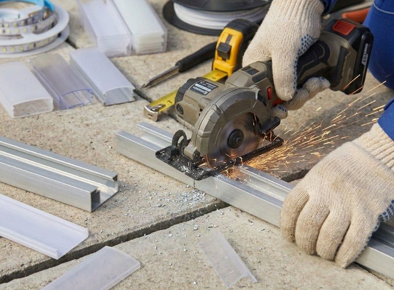
Mitre saw with a non-ferrous metal blade: this is the single most important tool for cutting led profiles. A compound mitre saw allows you to make precise straight cuts and angled mitres with repeatable accuracy. The blade must be specifically designed for non-ferrous metals, typically a TCT (tungsten carbide tipped) blade with a high tooth count (80 teeth or more on a 250 mm / 10-inch blade) and a negative rake angle. A negative rake angle prevents the blade from grabbing the aluminium and pulling it into the cut, which is a dangerous tendency with wood-cutting blades used on metal. A suitable blade costs between €30 and €80 and lasts for hundreds of cuts. Do not use a standard wood blade or an abrasive cut-off disc, a wood blade will produce a rough, burred edge and may kick the workpiece, while an abrasive disc generates excessive heat, leaves a blackened edge and fills the profile with abrasive grit that will scratch the led strip.
Hacksaw with a 32 TPI bi-metal blade: for on-site work where a mitre saw cannot be set up (tight spaces, occupied areas where noise is restricted, or when you only have one or two cuts to make), a quality hacksaw with a 32-teeth-per-inch (TPI) bi-metal blade produces a clean cut through aluminium profile. Use long, steady strokes at moderate speed. Clamp the profile securely in a portable vice or against a stable surface to prevent it shifting during the cut.
Fine-tooth hand saw (Japanese pull saw): some installers prefer a Japanese-style pull saw for very precise aluminium cuts. The thin kerf and fine teeth produce an exceptionally clean cut with minimal burring. This is particularly useful when cutting diffuser covers, which are made of polycarbonate or acrylic and can crack if subjected to aggressive sawing.
Sharp scissors or purpose-made led strip cutter: led strips are cut at marked points using a sharp pair of scissors or, for higher precision, a dedicated led strip cutting tool. Standard household scissors can work but often produce a slightly ragged edge; a pair of sharp, straight-blade electronics scissors or micro-shears delivers a cleaner result.
Measuring and marking tools
Steel tape measure (5 m or 8 m): as discussed, a steel tape is essential for accurate measurement. Choose one with a locking mechanism and a clear, easy-to-read scale marked in millimetres.
Spirit level (600 mm and 1200 mm): you will use the spirit level to ensure profiles are mounted perfectly straight and level. A 1200 mm level is ideal for long surface-mount runs, a shorter 600 mm level is useful for checking alignment in tighter spaces or around obstacles. A laser level can be a useful addition for very long runs, projecting a perfectly straight reference line across an entire wall or ceiling.
Combination square or try square: for marking 90° cuts and checking that mitre-saw settings are accurate before cutting the profile, a combination square is invaluable. It also helps you verify that the cut end of a profile is perfectly square to its length.
Fine-tip permanent marker or scriber: mark cut lines directly on the aluminium with a fine-tip permanent marker (silver or white on anodised profiles, black on raw aluminium). A scriber leaves a finer line but is harder to see in low light.
Fixing and mounting tools
Cordless drill/driver: used for drilling pilot holes and driving screws when mounting clips, springs or the profile itself. A compact 12 V or 18 V drill/driver with a clutch is ideal, the clutch prevents over-tightening, which can deform thin-walled profiles.
Drill bits: you will need bits appropriate to the substrate: HSS twist drills for timber and metal, masonry bits for brick and concrete, and self-drilling / self-tapping screws for metal studs (which may not need a separate pilot hole). Carry a range from 2 mm to 6 mm.
Wall plugs and screws: select the correct type for the substrate: nylon plugs for masonry, toggle anchors or spring toggles for hollow plasterboard, direct screws for timber, and self-tappers for metal. The screws should be small enough to pass through the mounting clip holes without distortion.
Clamps: a pair of small quick-release bar clamps or spring clamps are essential for holding profiles steady during cutting and for clamping joints while you tighten grub screws.
Electrical tools
Wire strippers: a quality pair of wire strippers with calibrated notches for 0.5 mm² to 2.5 mm² cable. Avoid using a knife to strip wires — it nicks the conductor, creating a weak point that may fail under vibration or thermal cycling.
Soldering iron (optional but recommended): a temperature-controlled soldering iron (25–60 W, adjustable) with a fine chisel tip is the best tool for making permanent, low-resistance connections between led strip sections and between strip and feeder cables. Lead-free solder (Sn96.5/Ag3.0/Cu0.5 or similar) is recommended for longevity and compliance with RoHS regulations. If you prefer not to solder, you can use solderless clip connectors (discussed in Section 7.2), but be aware that soldered joints are more reliable, more compact and have lower contact resistance.
Multimeter: essential for checking voltage at the strip, verifying polarity, measuring current draw and diagnosing faults. A basic digital multimeter with DC voltage, resistance and continuity functions is sufficient.
Insulated terminal crimps and crimp tool (optional): for making neat, professional connections where solder is not appropriate — for example, connecting cables to driver output terminals.
Finishing and deburring tools
Deburring tool: a hand-held deburring tool with a swivelling blade (such as a Noga-style deburrer) quickly removes the sharp edge left on aluminium after cutting. This is a non-negotiable step: a burred edge will scratch the diffuser, cut your fingers and prevent end caps from seating properly. It takes ten seconds per cut and makes the difference between a professional and an amateur finish.
Fine flat file (second-cut): for smoothing the cut face of the profile after deburring, a fine flat file removes any remaining irregularities. A half-round file is useful for cleaning the inside of the profile channel.
Fine-grit sandpaper (240–400 grit): for a final polish of the cut edge, a few strokes with fine sandpaper wrapped around a flat block produces a smooth surface that end caps will press against neatly.
Personal protective equipment
Cutting aluminium produces sharp swarf (chips) and fine dust. Always wear safety glasses, close-fitting work gloves (cut-resistant gloves are ideal) and hearing protection when using a power saw. If using a mitre saw indoors, a dust mask rated FFP2 or higher is advisable to protect against fine aluminium particles. Keep the work area clean, aluminium swarf on the floor is a slip hazard and can scratch finished surfaces if walked around the site on your boot soles.
How to cut aluminium led profiles — Complete method
Cutting is the first physical operation you perform when you install aluminium led profiles on site, and it sets the tone for everything that follows. A clean, accurate, burr-free cut means the profile fits perfectly, the joint sits flush, the end cap presses on squarely and the diffuser slides into the channel without catching. A rough, inaccurate or angled cut causes visible gaps, misaligned joints, scratched diffusers and a general appearance of poor workmanship that no amount of adjustment can fully correct. This section provides a comprehensive method for how to cut aluminium led profiles using different tools, different angles and different profile geometries, giving you the knowledge to handle any situation you encounter on a live job.
Understanding aluminium extrusion metallurgy
Most led profiles are extruded from 6063-T5 aluminium alloy, an alloy chosen for its excellent extrudability, good surface finish, adequate strength and high thermal conductivity. In its T5 temper (artificially aged after extrusion), 6063 has a tensile strength of approximately 185 MPa and a Brinell hardness of about 60 HB. This makes it significantly softer than steel but harder than pure copper, and it behaves in a specific way under a cutting tool: it is prone to smearing and burring rather than chipping. This means the choice of blade, speed and feed rate is critical to achieving a clean cut without the aluminium “loading” the blade teeth or tearing at the exit point of the cut.
Anodised profiles, those with a hard, coloured oxide layer (typically 10–25 µm thick for architectural anodising), require slightly more care because the anodised layer is harder than the underlying aluminium and can chip at the cut edge if the blade is too aggressive. When cutting anodised profiles, use a sharp blade with a higher tooth count and reduce your feed rate slightly.
Choosing the right blade
The blade you use to cut aluminium led profiles is the single biggest factor in cut quality. Here is a comparison of common blade options.
| Blade type | Tooth count (250 mm) | Rake angle | Cut quality in aluminium | Recommended |
|---|---|---|---|---|
| TCT non-ferrous metal blade | 80–100 | Negative (−5° to −6°) | Excellent — clean, burr-free | Yes — first choice |
| TCT general-purpose crosscut blade | 60–80 | Positive (+10° to +15°) | Fair — some burring and grabbing | Acceptable if non-ferrous blade unavailable |
| TCT rip blade | 24–40 | Positive (+15° to +20°) | Poor — aggressive, tears aluminium | No |
| Abrasive cut-off disc | N/A | N/A | Very poor — heat, discolouration, grit | No |
| Hacksaw blade (32 TPI bi-metal) | 32 TPI | N/A | Good — clean with steady technique | Yes — for hand cutting |
The message is clear: invest in a proper non-ferrous TCT blade. It is the single best upgrade you can make to your cutting setup and it will pay for itself many times over in time saved on deburring and in the quality of the finished installation when you install aluminium led profiles.
Mitre saw technique: step-by-step
The following procedure describes how to cut aluminium led profiles accurately using a mitre saw. Follow each step in order.
Step 1 — Set up your saw: place the mitre saw on a stable, level surface at a comfortable working height. If using a saw stand with roller supports, adjust them to support the profile along its full length so it does not sag or tip. Ensure the blade guard is operational and that the dust extraction bag or vacuum is connected. Verify that the mitre angle is set to 0° (straight cut) or to the required angle for mitre joints, and lock the setting.
Step 2 — Mark the profile: measure from the end of the profile to the required cut point and mark the profile with a fine-tip marker. Extend the mark across the face of the profile using a combination square so you have a visible line to align with the blade. Double-check the measurement.
Step 3 — Position and clamp the profile: place the profile on the saw bed with its flat base down and its open channel facing upward (this is the most stable orientation for most profile shapes). Push the profile firmly against the saw fence. Clamp the profile to the fence or bed using the saw’s built-in clamp or a separate quick-release clamp. Do not hold the profile by hand alone during the cut, aluminium can grab on the blade and jerk the workpiece, causing injury and a ruined cut.
Step 4 — Align the blade to the mark: with the saw unpowered, lower the blade gently until it is just above the cut mark. Check that the blade will cut on the waste side of the line (i.e., the kerf falls in the material you are removing, not in the finished profile). Adjust the profile position if needed and re-clamp.
Step 5 — Make the cut: start the saw and allow the blade to reach full speed before lowering it into the workpiece. Feed the blade down smoothly and steadily, do not force it. Let the blade do the work. The cut through a typical led profile (wall thickness 1.0–2.0 mm) takes only 1–2 seconds. Hold the blade down at the bottom of the cut for a moment to ensure a clean exit on the underside of the profile, then raise the blade and allow it to stop fully before moving the workpiece.
Step 6 — Inspect the cut: remove the profile from the saw and inspect the cut face. It should be smooth and square, with no visible burrs on the outer edges. If you see small burrs, proceed to deburring (Section 4.6). If the cut is angled or rough, check your blade condition and clamp setup before making the next cut.
Hacksaw technique for on-site work
When you need to cut aluminium led profiles on site and cannot use a mitre saw, perhaps because of noise restrictions, access limitations or because you only have a handful of cuts to make, a hacksaw produces excellent results with the right technique.
Clamp the profile: use a portable vice, a Workmate-style bench or at minimum two clamps holding the profile to a stable surface. The profile must not move during the cut. Clamp it close to the cut line (within 20–30 mm) so there is minimal vibration.
Score a starting groove: place the blade on the cut mark and draw it backward (away from you) two or three times with light pressure to create a shallow groove. This prevents the blade from wandering when you start the forward stroke.
Saw with long, steady strokes: use the full length of the blade, applying moderate forward pressure and almost no pressure on the return stroke. Keep the blade straight and aligned with the cut mark. Do not rush: a hurried, short-stroke technique generates heat, clogs the blade and produces a ragged cut. Aim for 40–60 strokes per minute.
Support the offcut: as the cut nears completion, the offcut piece may bend downward under its own weight, causing the aluminium to tear at the last millimetre. Support the offcut with your free hand (wearing gloves) or rest it on a surface to prevent this.
After cutting, deburr and file the cut face exactly as you would after a mitre saw cut.
Cutting profiles for 45° and 90° mitres
Some installations require mitred joints: for example, when two profiles meet at a corner and the designer wants a seamless 90° turn without an external angular joint connector. In this case, each profile is cut at 45° and the two mitred ends butt together to form a right angle. Cutting mitres on led profiles demands high accuracy because even a half-degree error opens a visible gap at one side of the joint.
Set your mitre saw to exactly 45.0° using a precision protractor or digital angle gauge, not the saw’s built-in scale (which is often only accurate to ±1°). Make a test cut on a scrap piece of profile and check the angle with a combination square set to 45°. Adjust the saw until the test cut is perfect, then cut your production pieces.
When two mitred profiles are brought together, the led strip inside must be bridged across the joint. This usually means soldering a short flexible wire between the end of the strip in one profile and the start of the strip in the other, or bending a flexible COB strip around the corner if the led type permits it. Allow extra strip length (10–15 mm per side) at each mitred end to accommodate the connection. We will discuss connecting led strips across joints in detail in Section 6.6.
Deburring: why it is non-negotiable
Every cut through aluminium leaves a burr, a thin lip of displaced metal along the cut edge. On an led profile, this burr causes several problems if left in place. It prevents end caps from seating flush. It scratches the polycarbonate diffuser as you slide it into the channel, leaving permanent white marks on a transparent or satin cover. It can cut your fingers during handling. And on a visible surface-mount profile, a burr catches the light and looks unsightly. Deburring every cut is not optional, it is a fundamental quality step that takes seconds and prevents multiple downstream problems.
Use a deburring tool to sweep the blade around both the outside and inside edges of the cut. Follow up with two or three passes of a fine flat file across the cut face, working in one direction (not back-and-forth, which can reload the burr). Finish with a wipe of fine sandpaper if a smooth, polished edge is required for a visible application. Blow out any swarf from inside the profile channel with a puff of compressed air or a firm breath.

Cutting diffusers separately
In most cases, the diffuser cover should be cut separately from the profile rather than being cut together. Polycarbonate diffusers (the most common material) are tough but can crack or chip if subjected to the aggressive action of a metal-cutting blade. Here are two effective methods for cutting diffusers.
Method A — Fine-tooth handsaw: mark the diffuser at the required length, clamp it gently (not too tightly because polycarbonate deforms under excessive clamping pressure) and cut with a fine-tooth handsaw or Japanese pull saw. Use slow, steady strokes to avoid generating heat, which can melt the polycarbonate and leave a rough, frosted edge.
Method B — Score and snap: for thin diffusers (under 1.5 mm thick), you can score a line across the surface with a sharp utility knife using a straight edge, then bend the diffuser along the score line to snap it cleanly. This works best with flat diffusers and less well with curved or domed profiles.
After cutting, smooth the edge of the diffuser with fine sandpaper (320–400 grit) to remove any roughness. Cut the diffuser 1–2 mm shorter than the profile so that it does not protrude beyond the end cap — a protruding diffuser looks untidy and is easily damaged.
Common cutting mistakes and how to avoid them
The following table summarises the most common mistakes installers make when cutting led profiles, along with the cause and the solution. Review this table before you start cutting on site, it is much easier to avoid a mistake than to fix one.
| Mistake | Cause | Consequence | Prevention |
|---|---|---|---|
| Profile cut too short | Measuring from the wrong reference point, not accounting for end caps, parallax error on tape measure | Visible gap at one or both ends, cannot be fixed without a new piece of profile | Measure from a consistent datum, deduct end cap thickness, double-check before cutting |
| Profile cut too long | Not accounting for wall-to-wall fit, measuring outside the profile instead of inside | Profile bows or buckles when forced into space, will not lay flat | Measure the actual installation space, not the profile, test-fit before final mounting |
| Cut is not square | Profile not clamped properly, blade not at true 0°, profile slipped during cut | Gap visible at joint, end cap does not seat flush, light leaks at end | Clamp profile firmly, verify saw angle with a square, use test cuts |
| Burrs left on cut edge | Skipping the deburring step, using a worn blade | Scratched diffuser, cut fingers, end cap will not fit, unprofessional appearance | Always deburr and file, replace blade when cut quality degrades |
| Aluminium swarf inside the profile channel | Cutting with the channel facing the blade, not cleaning after cutting | Swarf scratches led strip and diffuser, can short-circuit exposed solder pads on the strip | Cut with channel facing up or away from blade, blow out channel after every cut |
| Diffuser cracked during cutting | Using a coarse blade, cutting too fast, excessive clamping pressure | Diffuser must be replaced, wasted material | Use a fine-tooth saw, slow steady strokes, gentle clamping |
How to cut led strips to match profile lengths
Once you have cut your aluminium led profiles to length, the next task is to cut the led strip itself to match. This might seem straightforward, but led strips are electronic circuits and they can only be cut at specific points without causing damage. Cutting in the wrong place destroys a section of leds and may create a short circuit. This section explains how to identify cut points on different types of led strip, how to make clean cuts and how to match strip length to profile length when the two do not align exactly. The led strips available from Lightingline.eu are manufactured with clearly marked cut points, making this process straightforward as long as you follow the rules.
Locating cut points on led strips
Every led strip has designated cut points at regular intervals along its length. These are usually indicated by a scissor icon printed on the strip, or by a pair of exposed copper pads (sometimes marked with a dashed line) between two groups of leds. The spacing of cut points depends on the strip’s electrical design: for a 12 V strip cut points are typically every 25 mm or 50 mm (every 3 leds), for a 24 V strip cut points are usually every 50 mm or 100 mm (every 6 leds), for a 48 V strip they may be every 100 mm or 200 mm. You must only cut at these designated points. Cutting between points severs the parallel circuit of a group of leds, causing that group to fail and potentially creating a short circuit.
Before cutting, unroll the strip and lay it alongside the profile. Mark the strip at the point closest to the desired length that coincides with a cut point. If the nearest cut point leaves the strip slightly shorter than the profile, accept the short gap: it will be hidden by the end cap. Never stretch or force a strip to make up a shortfall.
Cutting single-colour strips
Single-colour led strips (white, warm white, cool white or a single colour) are the simplest to cut because they have only two conductors: positive (+) and negative (−). At each cut point, you will see two copper pads. Use sharp scissors or micro-shears to cut cleanly through the centre of the copper pads. Do not cut to one side of the pads, you need to leave enough copper on both the strip you are keeping and the offcut to allow a connection to be soldered or clipped on later.
Cutting tunable white and RGB strips
Tunable white (dual-white) strips have three or four conductors (typically +V, warm white, cool white, and sometimes a common negative). RGB strips have four conductors (+V, R, G, B or common anode/cathode variations), and RGBW strips have five. The cut points on these strips are wider to accommodate the additional pads. The same rule applies: cut through the centre of the marked cut point, ensuring each pad retains enough exposed copper for a connection. Be especially careful with RGBW strips, where the pads are smaller and closer together, a crooked cut can short adjacent pads.
Cutting COB led strips
COB (Chip-on-Board) led strips have become increasingly popular because they produce a perfectly uniform, dot-free line of light without needing an opaque diffuser. However, COB strips have narrower and more closely spaced cut points than traditional SMD strips, and the cut must be very precise. Use micro-shears rather than scissors, and cut squarely across the strip. A diagonal or ragged cut on a COB strip can damage the phosphor layer and cause colour inconsistency at the cut end.
Matching strip length to profile length
In a perfect world, the cut point spacing on the led strip would divide exactly into the length of every profile you cut. In practice, it rarely does. Here is how to handle the discrepancy.
Strip shorter than profile: if the nearest cut point leaves the strip 5–20 mm shorter than the profile, this is acceptable. The end cap will cover the gap, and the small dark section at the end of the profile is invisible once the cap is fitted. If the gap exceeds 20 mm, consider extending the strip with a short jumper wire soldered to the last cut point, adding a small section of additional strip to fill the space.
Strip cut point falls past the profile end: do not fold the strip or allow it to protrude beyond the profile. Cut at the previous cut point, even though this leaves the strip slightly shorter. A strip protruding beyond the profile will be crushed by the end cap and may short-circuit.
Multiple profiles in a run: when a continuous light line spans several joined profiles, calculate the total run length first, then determine how many full strip segments (measured in cut-point intervals) fit within that length. Install one continuous strip across the joints where possible, cutting only at the ends of the total run. This eliminates mid-run electrical connections and dark spots at profile joints.
How to join aluminium led profiles — Mechanical connections
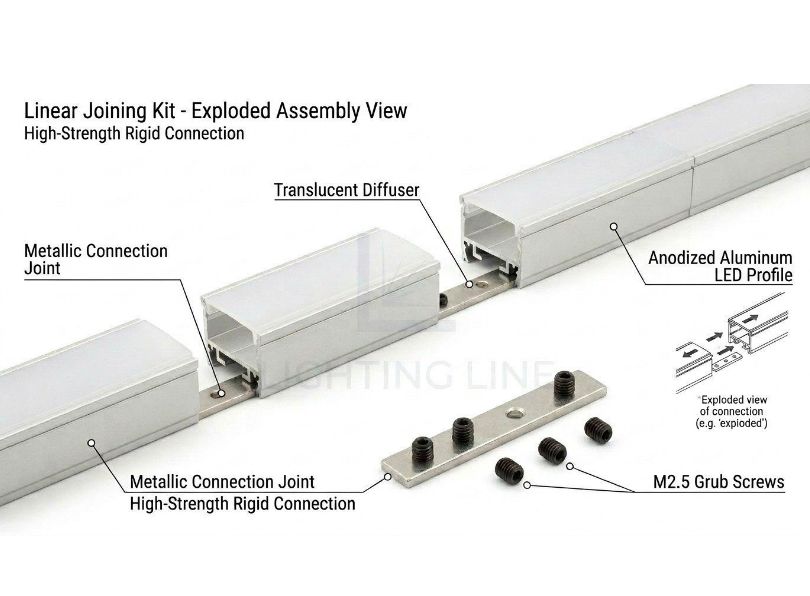
Architectural lighting designs frequently call for continuous lines of light that extend far beyond the length of a single profile bar (typically 2 or 3 metres from the factory). Corridors, perimeter coves, retail display runs and open-plan office ceilings can require 10, 20 or even 50 metres of unbroken light line. To achieve this, you must join multiple profile sections together on site using mechanical connectors designed for the purpose. This section explains how to join aluminium led profiles for straight runs, right-angle turns and other angular transitions, and how to ensure each joint is mechanically tight, thermally continuous and visually seamless once the diffuser is fitted.
Linear joints for straight runs
A linear joint connects two profile sections end-to-end in a straight line. The joint connector is a metal insert, typically a short length of aluminium or zinc alloy machined to slide tightly into the internal channel of the profile. Each end of the insert has a grub screw (set screw) that is tightened against the inside wall of the profile to lock it in place. The LLP-AC01-M from LightingLine is a purpose-designed linear joint that fits the standard profile channel.
Installation procedure: slide one end of the joint connector halfway into the first profile section. Tighten the grub screw on that end so the connector is locked to the first profile. Then bring the second profile up to butt against the first, and slide it onto the protruding half of the connector. Tighten the second grub screw. The two profiles should now be perfectly aligned, with no gap and no step between their top surfaces. Run your fingertip across the joint to check for any misalignment, even 0.5 mm of step will be visible under the diffuser because it creates a shadow line.
Angular joints: 90° horizontal
When a profile run needs to turn a horizontal corner (for example following the perimeter of a room at ceiling level) a 90° horizontal joint is used. The LLP-AC03-M is a dedicated 90° horizontal angular joint that connects two profiles at a right angle on the same plane. This joint has two arms set at 90° to each other, each arm sliding into one of the two profile sections. The key to a clean corner joint is ensuring both profiles are cut to the correct length so that they meet the joint body without a gap on either side.
Measure from the wall (or the end of the previous profile section) to the centre point of the corner, then subtract half the body width of the angular joint. This gives you the cut length for each profile leading into the corner. Test-fit the assembly dry before final mounting.
Angular joints: 90° vertical
Where a profile transitions from a wall to a ceiling (or from a ceiling to a different plane), a 90° vertical joint is required. The AC04-M serves this purpose, connecting two profiles at a right angle in the vertical plane. The installation technique is the same as for horizontal joints: measure to the corner centre, subtract the joint body offset, cut, and assemble dry before fixing.
Angular joints: 120° and custom angles
Not all architectural geometries involve right angles. Vaulted ceilings, sloped bulkheads and faceted walls may require 120° transitions or other non-standard angles. LightingLine offers AC02-M 120° horizontal joints for these situations. For truly custom angles, you have two options: either mitre-cut the profiles at the required angle and butt them together with a flat plate or internal spline for reinforcement, or use a flexible profile section if available.
Tightening joints: torque, alignment and thermal continuity
A loose joint is one of the most common causes of problems when you install aluminium led profiles: a joint that is not fully tightened can work loose over time due to thermal expansion and contraction cycles, causing the two profile sections to separate slightly. This creates a visible dark spot in the light line, allows dust to enter the channel, and breaks the thermal continuity between the two sections , meaning the area of the strip near the joint receives less effective heat sinking.
When tightening grub screws on joint connectors, use the correct hex key (Allen key) and tighten firmly but not excessively, you are compressing a small screw against the inside of a thin-walled aluminium extrusion, and over-tightening can strip the thread or deform the profile wall. A good rule of thumb is to tighten until the joint is fully rigid with no play, then give the screw an additional quarter-turn. Check the alignment of the diffuser channel across the joint, the two channels must be perfectly co-linear so the diffuser can slide through the joint without catching.
Bridging the led strip across a joint
Once the mechanical joint between two profiles is secure, you need to ensure the led strip is electrically continuous across the joint. If you are running a single continuous strip through two joined profiles, the strip simply passes through the joint, no additional connection is needed (this is the preferred approach for linear joints). If the strip must be interrupted at the joint (for example, at a corner where the strip cannot bend), you will need to solder or clip-connect a short bridge cable between the two strip ends. Use flexible silicone-insulated wire of the same gauge as the strip’s conductors (typically 0.5 mm² or 22 AWG) and keep the bridge as short as possible (ideally under 30 mm) to minimise the dark gap. An opal or satin diffuser will help conceal a small dark spot at the joint, whereas a transparent diffuser will reveal it.
Connecting led strips — Electrical wiring inside the profile
With the profiles cut, joined and ready for mounting, the next critical task is the electrical work: connecting the led strip sections to each other and to the led driver. This is where the electrician’s expertise becomes paramount. Incorrect wiring does not merely produce a non-functional light, it can damage the led strip, overheat the driver or, in a worst case, create a fire hazard. This section covers every aspect of connecting led strips inside profiles, from soldering technique to solderless connectors, wire gauge selection and polarity verification. If you are a fit-out installer or plasterboard contractor rather than a qualified electrician, this section will help you understand what the electrician needs when they arrive to complete the wiring, and how to prepare the installation so the electrical connection goes smoothly.
Soldered connections: when and how
Soldering remains the gold standard for connecting led strips: a properly soldered joint has the lowest possible contact resistance, occupies minimal space inside the profile, withstands vibration and thermal cycling, and will not work loose over the lifetime of the installation. If you have the skill and the equipment, always prefer soldering over solderless connectors for permanent installations.
Equipment needed: a temperature-controlled soldering iron set to 320–350 °C (higher temperatures risk damaging the strip’s PCB and lifting the copper pads), a fine chisel tip (2–3 mm wide), lead-free solder wire (0.8 mm diameter is ideal for strip work), flux-cored or with a separate flux pen, and helping hands or a clamp to hold the strip steady.
Procedure
- Tin the copper pads on the strip: apply a small amount of solder to each pad, holding the iron tip against the pad for 1–2 seconds until the solder flows smoothly and covers the pad with a thin, shiny layer. Do not overheat the pad — if you hold the iron on for more than 3 seconds, the pad may delaminate from the PCB substrate, ruining the strip.
- Tin the ends of the connecting wires: strip approximately 3 mm of insulation from each wire, twist the strands together and apply solder to coat them.
- Join the wire to the pad: hold the tinned wire against the tinned pad and touch the soldering iron to the junction for 1–2 seconds until the solder on both surfaces melts and flows together. Remove the iron. The joint should be smooth, shiny and concave (a good solder joint looks like a small, gently curved fillet). A dull, lumpy or balled joint indicates insufficient heat or contaminated surfaces: reheat and reflow, or desolder and start again.
Fourth, apply a small piece of heat-shrink tubing or liquid electrical tape over each solder joint to insulate it and prevent shorts against the aluminium profile.
Solderless clip connectors
For installers who do not solder, or for rapid connections in time-critical installations, solderless clip connectors provide a viable alternative. These small plastic clips grip the copper pads on the led strip using spring-loaded metal teeth, making an electrical connection without heat. Solderless connectors are faster to fit but have higher contact resistance, take up more space inside the profile and are more prone to failure from vibration, thermal cycling or if the strip is not perfectly flat in the connector jaws.
To use a clip connector: open the clip, slide the strip into the jaws until the copper pads align with the metal teeth, then close the clip until it locks. Gently tug the strip to confirm it is held securely. For strip-to-wire connections, use a connector variant with a wire clamp on one side and a strip clip on the other.
A few practical tips: always clean the copper pads with isopropyl alcohol before inserting the strip into a clip connector — any oxidation or residue on the pads will increase contact resistance. Ensure the strip is cut cleanly and squarely so the pads sit flat in the jaws. If you are joining two strip sections back-to-back (strip-to-strip), ensure there is enough slack in the strip on both sides of the connector to accommodate any thermal expansion without pulling the strip out of the clip.
Wire gauge selection and voltage drop
The wires connecting the led driver to the strip, and any jumper wires between strip sections, must be sized correctly to carry the required current without excessive voltage drop or overheating. The following table provides guidance on wire gauge selection for common installation scenarios.
| Application | Typical current | Run length (one way) | Recommended wire gauge |
|---|---|---|---|
| 24 V strip, 10 W/m, 5 m run | ~2.1 A | Up to 5 m | 0.75 mm² (18 AWG) |
| 24 V strip, 14.4 W/m, 5 m run | ~3.0 A | Up to 5 m | 1.0 mm² (17 AWG) |
| 24 V strip, 20 W/m, 5 m run | ~4.2 A | Up to 5 m | 1.5 mm² (15 AWG) |
| 12 V strip, 14.4 W/m, 3 m run | ~3.6 A | Up to 3 m | 1.0 mm² (17 AWG) |
| Long feeder from driver (any strip) | Varies | Over 10 m | 1.5–2.5 mm² (15–13 AWG) — calculate voltage drop |
| Short jumper between strip sections | Same as strip current | Under 0.3 m | 0.5 mm² (20 AWG) minimum |
Voltage drop is the silent enemy of led strip installations: at low voltages (12 V and 24 V), even small resistances in cables and connections cause a measurable drop in voltage at the far end of the strip, which manifests as a visible reduction in brightness and a shift in colour temperature. We cover voltage drop calculations fully in Section 14, but the basic rule is this: use the shortest cable runs you can, use the thickest wire that will fit inside the profile, and for any run over 5 metres, consider feeding power from both ends of the strip.
Connecting led profiles to drivers and dimmers
The led driver (power supply) converts mains AC voltage (230 V in Europe) to the low-voltage DC required by the strip (typically 12 V, 24 V or 48 V). The connection from the driver’s output terminals to the led strip must be made with correct polarity, positive (+) to positive, negative (−) to negative. Reversing polarity will not damage most modern led strips (they simply will not light up), but on some older or lower-quality strips it can cause permanent damage.
If the system includes a dimmer, it is typically installed between the driver and the strip (for PWM dimmers) or between the mains supply and the driver (for phase-cut or TRIAC dimmers that require a dimmable driver).
Make all connections outside the profile where possible, at the driver terminals and at the point where the cable enters the profile through the end cap. This keeps the inside of the profile clean and uncluttered, and makes future servicing easier.
Polarity, colour codes and common wiring errors
led strips and their drivers follow a simple colour code for wiring, but mistakes are still common, especially in multi-channel (RGB, RGBW, tunable white) systems where there are more conductors to keep track of.
| Strip type | Conductors | Typical wire colour code |
|---|---|---|
| Single colour (white) | 2 (V+, V−) | Red = V+, Black = V− |
| Tunable white (CCT) | 3 (V+, Warm, Cool) | Red = V+, White = Cool White, Yellow = Warm White |
| RGB | 4 (V+, R, G, B) | Red = V+, then R/G/B wires by colour |
| RGBW | 5 (V+, R, G, B, W) | As RGB plus White wire for white channel |
Common wiring error #1: reversed polarity. The strip will not light up. Check with a multimeter before panicking — the fix is simply swapping the two wires at the connection point.
Common wiring error #2: swapped channels on RGB/RGBW strips. The strip lights up but the colours are wrong — red appears when you expect green, for example. This is caused by connecting the R, G and B wires to the wrong controller outputs. Methodically check each wire against the strip markings and the controller output labels.
Common wiring error #3: wrong voltage driver. Connecting a 12 V strip to a 24 V driver will immediately overheat and potentially burn out the leds. Connecting a 24 V strip to a 12 V driver will result in dim, warm-shifted light or no light at all. Always verify the strip voltage rating against the driver output voltage before connecting.
How to install aluminium led profiles on different surfaces
The surface to which you mount the profile determines the fixing method, the tools required and the level of preparation needed. This section provides detailed instructions for every common substrate type you will encounter when you install aluminium led profiles on site. Each sub-section covers the substrate characteristics, the appropriate fixing method, the step-by-step procedure and the pitfalls to watch out for.
Surface mounting on plaster, concrete and brick
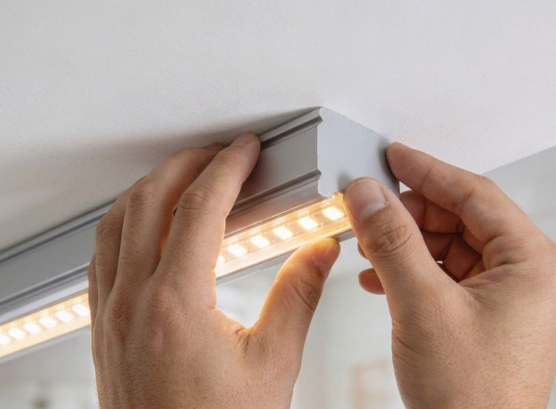
Surface mounting is the most straightforward method to install aluminium led profiles. The profile is fixed directly to the finished surface using mounting clips, adhesive or direct screw-through fixing. On plastered walls, concrete soffits and brick surfaces, the standard approach is to use mounting clips from the PRM-ES series, which are L-shaped or U-shaped metal or plastic brackets that screw to the wall and grip the profile.
Procedure: first, mark the line of the profile run on the surface using a spirit level and a pencil. Position the mounting clips along this line at 300–500 mm centres and mark the screw holes. Drill pilot holes using a masonry bit (typically 6 mm for a standard wall plug). Insert wall plugs. Screw the mounting clips to the surface, checking alignment with the spirit level as you go. Once all clips are secured, snap the profile into the clips, most clip designs allow the profile to be pressed in from above and held by spring tension. Check that the profile is straight by sighting along its length from one end.
On painted or finished surfaces, take care when drilling not to crack or chip the surrounding finish. Use a piece of low-tack masking tape over the drill point to prevent the drill bit from wandering and to protect the surface from the drill chuck.
Recessed installation in plasterboard / drywall
Recessed installations — where the profile is embedded into the plasterboard so that the diffuser is flush with the finished surface — are the most visually striking application of led profiles and are a key reason architects specify them. This is also the most demanding type of installation and the area where plasterboard contractors and electricians must work closely together. To install aluminium led profiles in a recessed plasterboard detail, the following sequence must be followed.
Step 1 — Prepare the framing: before the plasterboard is fixed, the profile must be mounted to the framing (timber joists, metal studs or a dedicated timber batten) at the correct position and depth. The top of the diffuser channel must be exactly flush with the finished face of the plasterboard. This means you need to know the plasterboard thickness (typically 12.5 mm or 15 mm) and set the profile depth accordingly.
Step 2 — Fix the profile to the framing: use mounting springs such as the PRM-SP01-M or PRM-SP02-M to secure the profile to the framing. Mounting springs have flexible arms that push against the back of the plasterboard once it is fixed, pulling the profile tight against the board face and holding it at the correct flush level. Space the springs at 300–400 mm centres.
Step 3 — Fix the plasterboard: the plasterboard is cut to accommodate the profile and fixed to the framing in the normal way. The edge of the plasterboard should butt up against the profile flanges (for flanged profiles) or leave a precise slot for trimless profiles. Trimless profiles from the PR-DW series (such as the PR-DW07-01) are designed specifically for this application, their flanges are perforated or textured to provide a key for plaster skim, and the finished result is a seamless slot of light with no visible frame.
Step 4 — Plaster and finish: the plasterer applies a skim coat over the plasterboard and up to the edge of the profile (or over the flanges of a trimless profile). Masking tape should be applied to the diffuser channel before plastering to prevent plaster entering the channel. Once the plaster is dry and sanded, remove the masking tape.
Step 5 — Install strip and diffuser: with the plastering complete, the electrician can now install the led strip inside the profile and fit the diffuser. The result is a clean, flush line of light that appears to glow from within the wall or ceiling itself, a premium architectural detail.
Mounting on timber and MDF
Timber and MDF (Medium Density Fibreboard) are common substrates in furniture, cabinetry, shelving and residential joinery applications. Mounting profiles on these materials is straightforward because you can screw directly into the substrate without wall plugs.
For timber: use small wood screws (3 mm × 16 mm or similar) through the mounting clip holes. Drill a 2 mm pilot hole to prevent the timber from splitting, especially near edges. For hardwoods, a pilot hole is essential.
For MDF: MDF holds screws well in its face but poorly in its edge. If mounting a profile to the edge of an MDF shelf, use longer screws and consider adding PVA glue to the screw hole before inserting the screw for additional holding power. Alternatively, use a two-part adhesive (such as a construction adhesive or acrylic foam tape rated for the weight of the profile) to bond the profile directly to the MDF surface.
Under-cabinet installations are one of the most popular applications for led profiles on timber and MDF surfaces. The profile is mounted to the underside of the wall cabinet, directing light downward onto the worktop. The angular profile is particularly effective here because its 45° angle directs the light forward and down, covering the work surface while keeping the led source out of the user’s direct line of sight.
Mounting on metal surfaces and suspended ceilings
In commercial environments, you may need to install aluminium led profiles on metal surfaces such as steel beams, aluminium ceiling grid members or steel shelving. Self-tapping screws or self-drilling screws are the standard fixing for metal substrates up to 2 mm thick. For thicker metal, drill a pilot hole first. Ensure the screw diameter matches the mounting clip holes.
For suspended ceilings with a T-bar grid, clip-on adapters are available that hook over the T-bar and provide a mounting point for the profile. Alternatively, the profile can be suspended on thin steel cables from the structural ceiling above, creating a pendant-style linear luminaire.
Corner and under-cabinet installation
Corner profiles are triangular in cross-section and mount into the 90° junction between two surfaces, typically where a wall meets a ceiling, or where the underside of a cabinet meets a vertical panel. The 45° angle of the diffuser face directs light diagonally, which is ideal for washing a work surface or wall with even illumination while shielding the led source from direct view.
To install aluminium led profiles in a corner position, first determine which of the two surfaces will bear the fixing screws (usually the horizontal surface, as it is easier to drill into). Apply a bead of silicone or construction adhesive along the inside of the other surface contact to provide additional support and vibration resistance. Screw the mounting clips to the primary surface at 300 mm centres, press the profile into the clips and check that it sits snugly into the corner with no rocking. The adhesive will cure and provide a secondary bond.
Suspended (pendant) profile installation
Suspended profiles hang below the ceiling on cables or rods, creating a pendant-style linear luminaire that is visible from below. This application is common in open-plan offices, restaurants, reception areas and retail spaces. The profile must be supported at regular intervals, typically every 1000–1500 mm, using thin steel suspension cables or rigid threaded rods attached to the ceiling structure above.
Each suspension point consists of a ceiling anchor (expansion bolt into concrete, or a toggle fitting for plasterboard), a cable or rod of the required length, and a gripper or bracket that clamps to the profile. Ensure all suspension points are level using a laser level, even a 2–3 mm height difference between two suspension points will be visible along the length of a suspended profile. Adjust the cable grippers until the profile hangs perfectly level and at the desired height.
Clip and spring spacing guidelines
The spacing of mounting clips or springs depends on the weight of the profile (including strip, diffuser and end caps), the rigidity of the profile and the orientation of the installation. The following table provides recommended spacings for common scenarios.
| Installation type | Profile weight category | Recommended clip / Spring spacing |
|---|---|---|
| Surface mount, horizontal (ceiling or shelf underside) | Light (slim profiles, e.g. PR-SL series) | 400–500 mm |
| Surface mount, horizontal | Medium (standard profiles) | 300–400 mm |
| Surface mount, horizontal | Heavy (large-section profiles, e.g. PR-CL02-07) | 250–300 mm |
| Surface mount, vertical (wall) | Any | 300–400 mm |
| Recessed in plasterboard | Any | 300–400 mm (springs) |
| Corner mount (45° profile) | Light to medium | 300–400 mm |
| Suspended (pendant) | Any | 1000–1500 mm (suspension cables) |
Selecting the right profile for the surface
Choosing the correct aluminium led profile is one of the most consequential decisions you will make on a lighting project. The profile must match the mounting surface, the desired aesthetic, the thermal demands of the led strip and the physical constraints of the installation space. LightingLine offers a specialised ecosystem of profiles tailored to specific mounting environments, and understanding which product to specify for each situation will save you time on site, eliminate compatibility problems and deliver a result that looks and performs exactly as the designer intended.
Plasterboard trimless profiles
For plasterboard (trimless) installations, use the PR-DW series (for example, the LLP-DW07-01). These profiles are specifically designed to be plastered over, allowing for “invisible” architectural integration where the light source is flush with the wall or ceiling without visible flanges. The flanges of the PR-DW series are perforated or textured to provide a mechanical key for the plaster skim coat, and the profile body sits recessed behind the plasterboard surface so that only the diffuser slot is visible once the wall is finished. This creates a seamless, minimalist line of light that appears to emerge directly from the architecture, a detail that is increasingly specified by architects and interior designers for high-end residential, hospitality and commercial projects.
Key considerations when installing PR-DW series profiles: ensure the void behind the plasterboard is deep enough to accommodate the full profile body (check the profile datasheet for minimum recess depth). Coordinate closely with the plasterboard contractor, the profile must be fixed to the framing before the board is installed, and the board must be cut to align precisely with the profile edges. Mask the diffuser channel during plastering to prevent plaster ingress.
Surface-mounted slim profiles
For surface mounting, the PR-SL series provides ultra-slim options. For instance, the LLP-SL13-02 is only 5 mm high, making it ideal for tight spaces where minimal visual impact is required. This series is perfect for under-cabinet lighting, inside wardrobes and cupboards, along shelving, and in any location where the profile must be as unobtrusive as possible. Despite their slim dimensions, these profiles still provide adequate heat dissipation for led strips up to approximately 10–12 W/m, which covers the vast majority of accent and task lighting applications.
Surface-mount profiles are the easiest to install aluminium led profiles on site because they require no recessing, no coordination with other trades and no specialised framing. They simply screw or clip to the finished surface and are ready for the led strip and diffuser.
Corner and angular profiles
For corners and under-cabinet applications, the LLP-AN02 angular profile is the standard choice for directing light at a 45° angle. This effectively covers work surfaces while preventing user glare, the led source is angled away from the user’s direct line of sight, producing comfortable, shadow-free task illumination. This profile mounts into any 90° junction (wall/ceiling, wall/shelf underside, cabinet/backsplash) using standard clips or adhesive, and accepts the same range of diffuser covers and end caps as other profiles in the LightingLine ecosystem.
Large-section profiles for high-power applications
When the led strip wattage exceeds 20 W/m, as it does for high-output linear lighting in commercial, retail and industrial applications, the profile must have a large enough cross-section to dissipate the additional heat safely. The LLP-CL02-07 (50 × 75 mm) is designed for exactly this purpose, with a massive thermal mass that keeps led junction temperatures within safe limits even at sustained high-power operation. Profiles with internal heat sinks or finned surfaces provide even greater thermal capacity. When you install aluminium led profiles for high-power applications, always check the profile manufacturer’s recommended maximum wattage per metre and ensure the strip’s power consumption falls within that rating.
Joining profiles for continuous runs — Detailed procedures
Creating long, seamless lines of light or navigating corners requires joining multiple aluminium led profile sections together using specialised metal mechanical joints. The quality of each joint directly affects the visual continuity of the light line, the structural integrity of the profile run and the thermal path for heat dissipation. This section provides detailed, product-specific procedures for every joint type in the LightingLine range.
Linear joints
The LLM-AC01-M linear joint is used to securely align and connect two straight sections of profile end-to-end. The joint body is a precision-machined metal insert that slides into the internal channel of both profile sections, locking them together with grub screws. This is the most commonly used joint when you install aluminium led profiles because most continuous runs require at least one linear splice to exceed the standard 2- or 3-metre bar length.
Installation steps: clean the inside of both profile ends to remove any swarf or dust from cutting. Insert one half of the LLM-AC01-M connector into the first profile and tighten the grub screw. Bring the second profile up to butt squarely against the first and slide it onto the protruding half of the connector. Align the diffuser channels carefully, then tighten the second grub screw. Check for any step or gap at the joint by running a finger across it and by sighting along the diffuser channel. Adjust as needed before final tightening.
90° Horizontal joints
The LLM-AC03-M is a 90° horizontal angular joint for transitions between two profiles on the same plane, typically when a profile run follows the perimeter of a room and needs to turn a corner. The joint body has two arms at 90° to each other, each arm inserting into one profile section. The critical step is measuring the profile lengths correctly to account for the body width of the joint at the corner point. Test-fit the entire corner assembly before fixing to the surface.
90° Vertical Joints
The LLM-AC04-M connects two profiles at a 90° angle in the vertical plane, for example, where a wall-mounted profile transitions to a ceiling-mounted profile. The installation technique mirrors the horizontal joint: measure, cut, test-fit, assemble and tighten. Pay particular attention to the alignment of the diffuser channel through the vertical transition any twist or misalignment will be highly visible because the eye follows the line of light around the corner.
120° Horizontal joints
For complex architectural geometries, faceted ceilings, angled bulkheads, non-orthogonal room layouts, LightingLine provides the LLM-AC02-M 120° horizontal joint. This joint enables profiles to follow obtuse-angle transitions smoothly. The installation procedure is the same as for the 90° joint, with the additional requirement that profile cut lengths must be calculated for the 120° geometry rather than 90°.
Stability, thermal continuity and diffuser alignment
Ensuring these joints are tightened securely is crucial: loose connections can lead to poor heat dissipation and misaligned diffusers. A joint that is not tight enough allows the two profile sections to shift relative to each other, creating a visible step in the diffuser line and a thermal gap that impedes heat flow from the led strip to the aluminium. Over time, thermal cycling (the daily heating and cooling of the leds) can cause a marginally tight joint to work loose, compounding the problem. After tightening all joints, perform a “wiggle test”, grip each side of the joint and try to move the profiles relative to each other. There should be zero movement. If there is any play, tighten the grub screws further or investigate whether the joint connector is the correct size for the profile.
On-site installation techniques
With the profiles cut, joined and the correct products selected, the focus shifts to the physical act of mounting and finishing the installation on site. This section consolidates the key on-site techniques that make the difference between a competent installation and an outstanding one, the techniques that clients notice and that earn repeat business and referrals.
Fixing methods: clips, springs and direct screw
Mounting clips (metal or plastic, such as the LLM-ES series) are the most versatile and widely used fixing method when you install aluminium led profiles. They allow the profile to be snapped in and out of the clips without tools, which is invaluable for maintenance, you can remove the profile to replace an led strip or clean the diffuser, then snap it back in place. Metal clips are more durable and provide a more positive grip than plastic clips, so they are recommended for commercial and high-traffic installations.
Mounting springs are designed specifically for recessed installations in ceilings. The spring arms extend outward from the profile body and press against the back face of the plasterboard or ceiling panel, pulling the profile flush with the surface. This is the standard fixing method for all recessed and trimless profile installations.
Direct screw fixing through the base of the profile is the simplest method but leaves screw heads visible inside the channel (under the led strip). This is acceptable for concealed installations (inside a cove or behind a pelmet, for example) but not for exposed profiles where the interior of the channel is visible through a transparent or satin diffuser.
Heat management for high-power led strips
For high-power led strips (over 20 W/m), consider using profiles with internal heat sinks or larger surface areas like the LLP-CL02-07 (50 × 75 mm) to ensure the longevity of the leds. The larger cross-section of these profiles provides a greater thermal mass and a greater surface area for convective heat loss to the surrounding air. In enclosed spaces (inside a bulkhead, for example), ensure there is adequate ventilation around the profile so that heat can escape — a profile surrounded by insulation will not dissipate heat effectively, regardless of its size.
Additional heat management measures for high-power installations: apply thermal interface material (thermal paste or high-conductivity adhesive tape) between the led strip and the profile base to improve thermal coupling. Do not stack multiple strips inside a single profile unless the profile is rated for the combined wattage. Avoid running high-power strips at maximum output for extended periods in high ambient temperature environments (above 35 °C) — derate the strip output or choose a higher-wattage profile to compensate.
Finishing with end caps
Always use the correct model-specific end caps to protect the strip from dust and to hide the cut edges of the aluminium. End caps are small but they make a disproportionate difference to the finished appearance of the installation. A profile without end caps looks unfinished and amateur, and the exposed aluminium edge is sharp enough to cut a finger. Many end caps feature pre-drilled holes for clean power cable entry, eliminating the need to drill through the cap on site (which often cracks or deforms it).
Match the end cap model to the profile model, they are not interchangeable between different profile series. Press the end cap firmly into the end of the profile until it is fully seated. If the cap feels loose, a small drop of cyanoacrylate (superglue) on the inside of the cap will secure it permanently.
Diffuser selection and light quality
The choice of diffuser (cover) significantly impacts the final aesthetic and light output when you install aluminium led profiles. The diffuser is the visible face of the entire installation, the surface that the client’s eye is drawn to, and it plays a decisive role in whether the light line appears professional and refined or rough and unfinished. LightingLine offers a comprehensive range of diffuser types to match every project requirement.
Transparent Diffusers
Transparent (FK) diffusers retain approximately 74 % of the original light output, making them the most efficient option in terms of raw lumen delivery. However, because they provide minimal scattering of the light, individual led chips are visible through the cover, the so-called “dotting” effect. Transparent diffusers are best suited for applications where maximum light output is the priority and the profile is mounted in a position where the diffuser face is not directly visible to occupants, for example, inside a cove, behind a pelmet or above a cabinet.
Satin diffusers
Satin (FS) diffusers offer a compromise between light output and visual uniformity. They retain roughly 52–56 % of the original flux while significantly reducing dot visibility. For most general-purpose architectural lighting applications (corridors, living spaces, offices and retail) satin diffusers represent the best balance of performance and aesthetics. They are the default recommendation for the majority of installations.
Opal / Opaque diffusers
Opal (FM) or opaque diffusers provide the smoothest, most uniform “dot-free” light, making the light line appear as a single, continuous glow with no visible individual leds. The trade-off is a higher degree of light loss, opal diffusers retain approximately 52–56 % of the original flux (with some models retaining up to only 44–48 %). Opal diffusers are the preferred choice for premium architectural installations where the diffuser face is directly visible and where visual perfection is expected: for example, in hotel lobbies, high-end retail, art galleries and residential feature lighting.
Lensed diffusers for beam control
For specialised projects where a controlled, directional beam is required rather than broad diffusion, lensed diffusers such as the LLP-06-XK1-L1 can narrow the beam to 60° for accent lighting. Lensed diffusers are used in display lighting, shelf lighting and any application where you need to direct the light precisely rather than spread it broadly. They combine the functionality of a profile diffuser with the optical control of a directional lens, eliminating the need for separate optical accessories.
Matching diffuser to application: decision matrix
| Application | Priority | Recommended diffuser | Approximate light retention |
|---|---|---|---|
| Cove / indirect lighting (profile hidden) | Maximum output | Transparent (FK) | ~74 % |
| General architectural lighting (profile partially visible) | Balance of output and uniformity | Satin (FS) | ~52–56 % |
| Feature lighting (profile fully visible) | Visual uniformity, dot-free | Opal (FM) | ~52–56 % |
| Accent / display lighting | Directional beam control | Lensed (e.g. PRD-06-XK1-L1) | Varies by lens |
| Under-cabinet task lighting | Even coverage, no glare | Satin (FS) or Opal (FM) | ~52–56 % |
Thermal management — Protecting your leds
Thermal management is the single most important factor in determining how long led strips will last in service. An led strip that is properly thermally managed will deliver its rated lumen output for 50,000 hours or more. The same strip operating at excessive temperatures may degrade to 70 % of its initial output in as few as 15,000 hours, less than three years of continuous operation. Every decision you make when you install aluminium led profiles affects thermal performance, and understanding the underlying physics will help you make better decisions.
Why heat kills leds
Leds do not fail suddenly like incandescent bulbs. Instead, they degrade gradually, a process called lumen depreciation. The rate of depreciation is exponentially related to junction temperature: for every 10 °C increase in junction temperature above the recommended maximum, the led’s useful life is approximately halved. This is a well-established relationship described by the Arrhenius equation and confirmed by extensive accelerated life testing by major led manufacturers. Keeping junction temperatures low is not about incremental improvement, it is about order-of-magnitude differences in lifespan.
Heat also causes colour shift. As an led junction runs hotter, its colour temperature shifts, typically becoming warmer (lower CCT) for phosphor-converted white leds. In an installation with multiple strips or multiple sections, even small temperature differences can create visible colour variations along the light line, undermining the visual uniformity that profiles and diffusers are designed to provide.
Profile cross-section and wattage ratings
The ability of an aluminium profile to dissipate heat is directly proportional to its surface area and thermal mass. A slim profile with a cross-section of, say, 12 × 5 mm has far less capacity to absorb and radiate heat than a large profile of 50 × 75 mm. Manufacturers typically specify a maximum recommended wattage per metre for each profile, based on maintaining a safe led junction temperature under normal ambient conditions (25 °C). Always check and respect this rating.
| Profile type | Typical cross-section | Approximate max wattage | Suitable applications |
|---|---|---|---|
| Ultra-slim surface mount (e.g. PR-SL13-02) | ~13 × 5 mm | 10–12 W/m | Accent, task, decorative |
| Standard surface mount | ~17 × 8 mm | 14–18 W/m | General architectural |
| Recessed / trimless (e.g. PR-DW series) | ~30 × 20 mm | 18–24 W/m | Architectural, feature |
| Large section (e.g. PR-CL02-07) | 50 × 75 mm | 30+ W/m | High-output commercial, retail |
Thermal paste and adhesive tapes
The thermal interface between the led strip and the profile base is a potential bottleneck. The 3M VHB adhesive backing on most led strips has a thermal conductivity of approximately 0.2 W/m·K, an order of magnitude lower than the aluminium itself. For low-power strips (under 10 W/m), the adhesive alone provides adequate thermal coupling. For higher-power strips, apply a thin layer of thermal paste (such as Arctic MX-4 or a generic silicone-based thermal compound rated at 4–8 W/m·K) to the base of the profile before pressing the strip down. Alternatively, use a high-conductivity thermal adhesive tape (rated above 1.0 W/m·K) in place of the standard 3M backing. This simple step can reduce junction temperature by 5–10 °C, significantly extending led life.
Ambient temperature considerations
The manufacturer’s wattage rating for a profile assumes a standard ambient temperature of 25 °C. In hotter environments, a kitchen above a hob, a conservatory in summer, an enclosed pelmet with no ventilation, or an outdoor installation in a Mediterranean climate, the ambient temperature may be 35–45 °C or higher. For every 10 °C above the standard 25 °C ambient, reduce the maximum strip wattage by approximately 10 % or step up to a larger profile. Conversely, in cooled environments (air-conditioned offices at 20 °C, for example), you have additional thermal headroom and can safely run strips closer to the profile’s maximum rating.
Voltage drop, power supply sizing and cable runs
Voltage drop is one of the most frequently overlooked aspects of led strip installation, and it is a major cause of callbacks and customer dissatisfaction. When you install aluminium led profiles, the electrical design is just as important as the physical installation. This section explains what voltage drop is, why it matters, how to calculate it and how to design your wiring to avoid visible brightness differences along the strip.
Understanding voltage drop in led strip systems
Every conductor has resistance. When current flows through a wire, some of the voltage is “dropped” (lost) across that resistance, according to Ohm’s Law: V_drop = I × R. In a 24 V led strip system, the nominal voltage at the driver is 24.0 V. By the time the current has travelled through the feeder cable, along the copper traces on the strip and back to the driver, the voltage at the far end of the strip may have dropped to 22.5 V or even lower. leds are sensitive to supply voltage: a 1 V drop on a 24 V system reduces the current through the leds by roughly 5–8 %, which the human eye perceives as a visible dimming at the far end of the strip compared to the end nearest the driver. On a 12 V system, the same absolute voltage drop represents twice the percentage loss, making 12 V systems much more sensitive to run length.
Calculating power supply capacity
To size the led driver correctly, calculate the total wattage of all led strips it will power and add a safety margin. The standard practice is to choose a driver rated for at least 120 % of the total strip wattage, ideally 130 % for long-life commercial installations. This headroom prevents the driver from operating at its thermal limit and extends its lifespan.
Example calculation: you have three 5-metre runs of 14.4 W/m led strip. Total wattage = 3 × 5 × 14.4 = 216 W. Minimum driver rating = 216 × 1.2 = 259 W. You would select a 300 W driver (the nearest available standard size above 259 W).
12 V vs 24 V vs 48 V systems
| System voltage | Typical max single-feed run | Voltage drop sensitivity | Best for |
|---|---|---|---|
| 12 V DC | 3–5 m | High — easily visible at 5 m | Short runs, accent lighting, furniture |
| 24 V DC | 5–10 m | Moderate — manageable with correct cable sizing | Most architectural and commercial applications |
| 48 V DC | 10–15+ m | Low — significantly reduced for long runs | Long continuous runs, high-power applications |
24 V is the recommended system voltage for the majority of installations. It offers the best balance of run length, cable cost, safety and product availability. 48 V systems are gaining popularity for very long runs and high-power commercial installations but require compatible drivers, strips and controllers.
Maximum run lengths and feed points
To keep voltage drop below the visible threshold (generally accepted as no more than 5 % of the nominal voltage), you must limit the maximum single-feed run length or add additional feed points. The most effective strategy is dual-end feeding: run a cable from the driver to both ends of the strip. This halves the effective run length for voltage drop purposes, allowing you to double the maximum strip length. Centre feeding (connecting the driver cable at the midpoint of the strip) achieves the same result. For very long runs (over 15 m even at 24 V), feed power at multiple points along the strip, every 5–8 metres.
Single-end feed: simple but limited
Single-end feeding is the simplest wiring configuration: one cable runs from the driver to one end of the led strip, and the current flows through the strip from that end to the far end. This works well for short runs where the voltage drop remains below the 5 % threshold. The maximum practical single-end feed length depends on the strip wattage, the strip voltage and the wire gauge, as shown in the table below.
| Strip voltage | Strip power (W/m) | Feeder wire gauge | Maximum single-end feed (approximate) |
|---|---|---|---|
| 12 V | 4.8 W/m | 0.75 mm² | 4.5 m |
| 12 V | 9.6 W/m | 0.75 mm² | 2.5 m |
| 12 V | 14.4 W/m | 1.0 mm² | 2.5 m |
| 24 V | 9.6 W/m | 0.75 mm² | 9.0 m |
| 24 V | 14.4 W/m | 1.0 mm² | 7.0 m |
| 24 V | 19.2 W/m | 1.5 mm² | 6.5 m |
| 48 V | 14.4 W/m | 0.75 mm² | 14.0 m |
| 48 V | 19.2 W/m | 1.0 mm² | 12.0 m |
These values are approximate and assume the feeder cable is short (under 2 m from driver to strip end). If the feeder cable itself is long, its resistance adds to the total voltage drop and the maximum strip length must be reduced accordingly.
Dual-end feed: doubling the range
Dual-end feeding runs a cable from the driver to both ends of the strip. The current entering each end only needs to travel half the strip length before meeting in the middle, so the voltage drop is reduced by approximately 75 % compared to single-end feed (because voltage drop is proportional to the square of the current path length in a distributed load). This effectively doubles or more the maximum practical strip length for a given voltage system and wire gauge. The wiring is slightly more complex, you need two cables from the driver to the profile, one entering each end cap, but the improvement in brightness uniformity is dramatic and well worth the extra cable.
Centre feed: same benefit, different routing
Centre feeding achieves the same electrical result as dual-end feeding but with a single cable entering the profile at its midpoint rather than two cables entering at each end. The cable passes through a hole drilled in the profile base or through a gap between two profile sections at the centre of the run. The current then flows outward in both directions from the centre, each half of the strip carrying only half the total current. This is particularly useful when the driver is located directly above the midpoint of the profile run (for example, in a ceiling void above a ceiling-mounted profile) and routing cables to both ends would be difficult.
Multiple feed points: the professional approach for long runs
For runs exceeding 15–20 metres, even dual-end feeding may not be sufficient to keep voltage drop within acceptable limits, particularly at higher strip wattages. In these cases, the professional approach is to feed power at multiple points along the run, every 5–8 metres, so that no section of strip is more than a few metres from a feed point. This requires running multiple low-voltage cables from the driver (or multiple drivers) to the various feed points, which in turn requires planning the cable routes during the early stages of the project. In a ceiling void, cables can be run along the top of the plasterboard or through cable trays. In a surface-mount installation, cables can be concealed behind a pelmet, inside a cove or within the wall cavity.
Multi-point feeding also has a reliability benefit: if one feed cable is accidentally damaged or disconnected, the strip sections served by other feed points continue to operate. This redundancy is particularly valuable in commercial and public installations where lighting failure may create safety or operational issues.
Dimming and control wiring inside profiles
Dimming is an increasingly standard requirement for led lighting, and the wiring for dimming must be planned and installed at the same time as the led strip and profile. Retrofitting dimming to an existing led profile installation is possible but significantly more disruptive and expensive than including it from the outset. This section covers the main dimming technologies and their wiring requirements when you install aluminium led profiles.
PWM dimming
Pulse Width Modulation (PWM) dimming is the most common and most reliable dimming method for led strips. A PWM dimmer rapidly switches the DC supply to the strip on and off at a frequency above the eye’s perception threshold (typically 500 Hz to 25 kHz), and by varying the ratio of on-time to off-time (the duty cycle), it controls the perceived brightness from 0 % to 100 %. PWM dimming preserves the colour temperature and colour rendering of the leds across the full dimming range, making it the preferred choice for colour-critical applications.
The PWM dimmer is installed between the led driver (which outputs constant-voltage DC) and the led strip. It requires DC wiring on both sides: input from the driver and output to the strip. The dimmer can be mounted outside the profile (in a ceiling void, switch cupboard or junction box) and connected to the strip via wires passing through the profile end cap. When you install aluminium led profiles in a residential setting, the PWM dimmer is typically wall-mounted in a standard back box, replacing the original mains dimmer switch. A constant-voltage driver is mounted remotely (in the ceiling void or cupboard), and the dimmed DC output runs to the profile.
Choosing the correct PWM frequency is important: low-frequency PWM (below 500 Hz) can cause visible flicker, especially in peripheral vision, and may produce audible buzzing from the led strip or driver. Higher frequencies (above 1 kHz) eliminate visible flicker but can sometimes cause electromagnetic interference with nearby audio or video equipment. For most residential and commercial installations, a PWM frequency between 1 kHz and 10 kHz provides the best balance of smooth dimming, silence and compatibility. Some premium PWM dimmers allow you to adjust the frequency — if yours does, start at 1.2 kHz and increase only if you observe interference.
Minimum dimming level varies between led strips. Some strips dim smoothly to 1 % or lower, while others may flicker or switch off abruptly below 5–10 %. This is a characteristic of the leds themselves, not the dimmer, and it depends on the forward voltage tolerance of the individual led chips. Before committing to a dimming system, test a sample of the actual led strip you plan to use with the actual dimmer, and verify that the dimming curve is smooth and the minimum level is acceptable to the client. Document this test, it protects you if the client later complains about the dimming performance.
PWM wiring best practices inside profiles
When running PWM-dimmed wiring through an aluminium led profile, ensure the wires are securely routed alongside the led strip without crossing over the leds or interfering with the adhesive backing. Use silicone-insulated wire rather than PVC-insulated wire inside the profile, because silicone insulation withstands the elevated temperatures inside the profile (typically 40–60 °C above ambient when high-power strips are running) without degrading. Route the wires along the base of the profile channel, underneath or beside the led strip, and secure them with a small dab of hot-melt glue every 300 mm to prevent them from lifting and pushing the diffuser. The wire entry point at the end cap should be sealed with a rubber grommet or a bead of silicone to prevent dust ingress and to provide strain relief.
DALI and 0-10 V integration
In commercial and institutional buildings, the lighting control system often uses the DALI (Digital Addressable Lighting Interface) protocol or the simpler 0–10 V analogue signal. These protocols control a DALI-compatible or 0–10 V-compatible led driver, which in turn adjusts its output voltage or current to dim the led strip. The DALI or 0–10 V wiring runs to the driver, not to the strip, so it does not pass through the profile. However, you must ensure the feeder cable from the driver to the strip is long enough to reach from the driver’s location (which may be in a central control panel) to the profile.
DALI wiring requirements are straightforward but must be followed precisely. DALI uses a two-wire bus (no polarity) that can be run alongside mains wiring in the same cable tray or conduit, which simplifies installation. The bus supports up to 64 devices on a single loop, with a maximum cable length of 300 metres using 1.5 mm² cable. Each DALI-compatible led driver is assigned a unique address, allowing individual control of each profile run from a central controller, building management system (BMS) or touch panel. When you install aluminium led profiles in a DALI-controlled environment, coordinate with the controls contractor to ensure that driver addresses are assigned and tested before the ceiling is closed up.
The 0–10 V system is simpler and cheaper than DALI but less flexible. A 0–10 V signal wire (two-conductor, typically 0.5 mm² to 1.0 mm²) runs from a wall-mounted dimmer or central controller to the 0–10 V input on the led driver. When the signal voltage is at 10 V, the driver runs at full output; when the signal drops to 0 V, the driver dims to its minimum level (which may be off or may be a low residual glow, depending on the driver design). 0–10 V wiring must be run separately from mains cables to avoid interference, because the low-voltage signal is susceptible to electrical noise. Use screened cable in environments with high levels of electromagnetic interference, such as near variable-speed drives or heavy switchgear.
Dimming protocol comparison for profile installations
| Feature | PWM (DC Side) | 0–10 V | DALI |
|---|---|---|---|
| Signal wiring to profile | No (signal is in DC output) | No (signal goes to driver) | No (signal goes to driver) |
| Individual addressing | No (one dimmer per zone) | No (one signal per zone) | Yes (up to 64 addresses) |
| Colour temperature change during dimming | Minimal | Depends on driver | Depends on driver |
| Typical minimum dim level | 1–5 % | 1–10 % | 0.1–1 % |
| Wiring complexity | Low (DC only) | Medium (separate signal pair) | Medium (bus wire, no polarity) |
| Cost per zone | Low | Low–Medium | Medium–High |
| Best suited for | Residential, small commercial | Small–medium commercial | Large commercial, institutional |
Wireless control: zigbee, bluetooth and Wi-Fi
Wireless dimming and control eliminates the need for dedicated control wiring between the switch and the driver. A small wireless receiver, compatible with Zigbee, Bluetooth Mesh, Wi-Fi or a proprietary protocol, is paired with the driver or installed inline between the driver and the strip. The receiver communicates with a wall switch, remote control or smartphone app. Wireless receivers are compact enough to fit inside the ceiling void or even inside the end of a larger-section profile, but they should not be sealed inside a fully enclosed space without ventilation as they generate a small amount of heat during operation.
Zigbee is the protocol of choice for larger wireless lighting installations because it operates on a mesh network (each device acts as a repeater, extending the range of the network automatically). A Zigbee-based led profile installation with twenty or thirty profile runs spread across a building will self-organise into a reliable mesh without any additional wiring. Zigbee receivers are typically powered from the 24 V DC supply feeding the led strip, simplifying installation when you install aluminium led profiles in retrofit projects where running new control wiring would be impractical.
Bluetooth Mesh is a newer alternative that works similarly to Zigbee but uses the Bluetooth radio already present in smartphones, which means the client can control the lighting directly from their phone without a dedicated hub or gateway. This makes Bluetooth Mesh attractive for residential projects and small hospitality installations. However, Bluetooth Mesh networks are typically smaller (limited to about 32,000 nodes in theory, but practical limits are lower) and less established in the commercial lighting market than Zigbee.
Wi-Fi receivers connect directly to the building’s Wi-Fi network and are controlled via a smartphone app or voice assistant (Alexa, Google Home, Apple HomeKit). Wi-Fi is the simplest option for the end user because it requires no hub or gateway, but it places additional load on the building’s Wi-Fi network, each receiver is a connected device. For installations with more than ten profile runs, a dedicated Wi-Fi access point or VLAN for lighting devices is advisable to prevent the lighting system from congesting the client’s main network.
Wireless receiver placement considerations
The physical placement of the wireless receiver affects signal quality and reliability. Aluminium profiles act as partial Faraday cages, they can attenuate radio signals if the receiver is placed inside the profile channel with the diffuser closed. For best results, mount the wireless receiver outside the profile in the ceiling void, and run a short DC cable through the end cap to the led strip inside the profile. If the receiver must be inside the profile (for aesthetic reasons or because there is no accessible ceiling void), ensure the diffuser is polycarbonate (radio-transparent) rather than aluminium, and test the wireless range on site before committing to the installation. Position the receiver near the end cap rather than in the middle of the profile, because the open end provides a better path for radio waves.
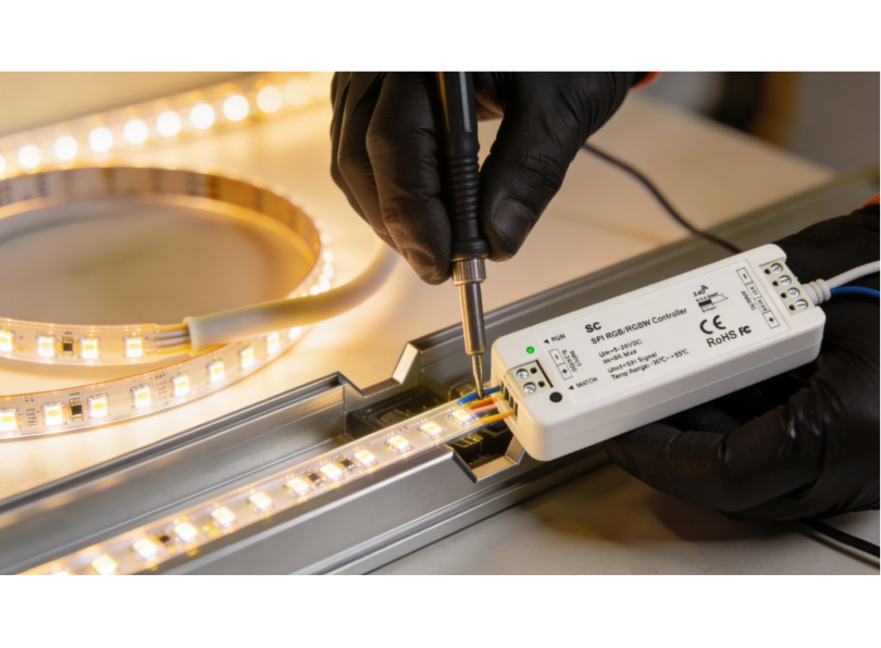
Placing controllers and receivers inside or outside the profile
Small inline controllers and receivers (for example, a compact PWM dimmer or a Zigbee receiver module) can sometimes be placed inside the profile itself if the profile cross-section is large enough and the module is slim enough. This can be convenient because it eliminates an external box and keeps all components within the profile channel. However, there are risks: the module adds heat inside the profile (compounding the thermal load from the led strip), it may interfere with the diffuser fit, and if it fails it requires disassembling the profile to access it. In general, it is better practice to mount controllers and receivers outside the profile in an accessible location, and route only the power cables through the profile end cap.
For large-section profiles such as the LLP-CL02-07 (50 × 75 mm), there is enough internal volume to accommodate a small receiver module alongside the led strip, provided the module is positioned at one end of the profile run and the thermal load from the strip does not exceed the profile’s dissipation capacity. Always verify the internal clearances with the actual components in hand, datasheet dimensions can be misleading because they do not account for connector bulk, wire bend radii or the space occupied by the adhesive backing of the led strip. A dry-fit assembly on the workbench before you install aluminium led profiles on site will reveal any interference issues.
Tunable white and dynamic colour control
Beyond simple brightness dimming, modern led strip installations increasingly require tunable white (the ability to adjust colour temperature from warm white, around 2700 K, to cool white, around 6500 K) or full dynamic colour (RGB or RGBW). These capabilities require additional wiring channels and compatible controllers.
Tunable white strips use two sets of leds, warm and cool, on the same strip, and a dual-channel controller varies the ratio of warm to cool to produce the desired colour temperature. The strip has four conductors (V+, warm white–, cool white–, and sometimes a common ground) and the controller needs two PWM output channels. When you install aluminium led profiles with tunable white strips, the four-conductor cable must be routed through the end cap and connected to the appropriate controller. Label the conductors carefully, there is no universal colour code for tunable white wiring, and swapping the warm and cool channels results in the strip getting cooler when the user dials warmer.
RGB and RGBW strips require a three-channel (RGB) or four-channel (RGBW) controller and correspondingly more conductors: five wires for common-anode RGB (V+, R–, G–, B–) or six for RGBW (V+, R–, G–, B–, W–). The increased number of conductors means that wire management inside the profile becomes more complex, and the cable entry point at the end cap must be large enough to accommodate the thicker cable bundle. Use multi-core flexible cable rather than individual wires to keep the installation tidy and to reduce the risk of conductor damage during diffuser fitting.
When routing multi-channel wiring through joints between profile sections, ensure that every conductor is bridged across the joint with sufficient slack to allow for thermal expansion. A loose or intermittent connection on just one channel (for example, the green channel in an RGB setup) will produce unpredictable colour shifts that are difficult to diagnose later.
Waterproofing and outdoor installations
Installing led profiles outdoors or in wet environments (bathrooms, kitchens, swimming pool areas) introduces additional challenges related to moisture ingress. Water and electronics are incompatible, and even a small amount of moisture inside a profile can corrode solder joints, short-circuit the strip and cause premature failure. This section explains how to protect the installation when you install aluminium led profiles in exposed or damp locations.
IP ratings explained
The IP (Ingress Protection) rating system classifies the degree of protection provided against solid objects (first digit) and liquids (second digit). For led profile installations, the relevant ratings are:
| IP rating | Protection level | Typical application |
|---|---|---|
| IP20 | Protected against objects larger than 12.5 mm; no water protection | Dry indoor environments only |
| IP44 | Protected against objects larger than 1 mm; protected against splashing water | Bathrooms (Zone 2 and above), covered outdoor areas |
| IP65 | Dust-tight; protected against water jets | Exposed outdoor, kitchens, shower rooms (outside direct spray) |
| IP67 | Dust-tight; protected against temporary immersion | Ground-level outdoor, pool surrounds |
| IP68 | Dust-tight; protected against continuous immersion | Underwater lighting (fountains, pools) |
Sealing end caps and cable entry points
For outdoor or wet-area installations, standard press-fit end caps are not sufficient, they must be sealed with silicone sealant or replaced with purpose-made waterproof end caps that incorporate an O-ring seal. Apply a bead of neutral-cure silicone (not acetic-cure, which corrodes copper) around the inside of the end cap before pressing it into the profile. Seal the cable entry point in the end cap with a cable gland or additional silicone. The cable gland approach is preferred because it provides both a waterproof seal and strain relief for the cable, preventing the cable from being pulled out of the end cap by accidental tugging during installation or maintenance.
When sealing an end cap, follow this procedure: first, clean all surfaces with isopropyl alcohol to remove any aluminium dust, grease or fingerprints that could prevent the silicone from adhering. Apply a continuous bead of neutral-cure silicone (clear or matching the profile colour) around the internal rebate of the end cap where it contacts the profile walls. Press the end cap firmly into the profile and wipe away any excess silicone that squeezes out. Allow the silicone to cure for at least 24 hours before exposing the installation to water. Do not use the led strip during the curing period, the heat from the strip can interfere with silicone curing and weaken the seal.
For cable entry points drilled through the end cap, insert a suitable IP68-rated cable gland (M8 or M10, depending on the cable diameter) and tighten the compression nut to grip the cable jacket firmly. If a cable gland is not practical due to space constraints, fill the drilled hole with silicone around the cable and allow it to cure. In either case, ensure there is a drip loop in the cable on the outside of the profile, a small downward loop that prevents water from tracking along the cable and entering the end cap.
Choosing profiles and strips for outdoor use
Select led strips with a silicone sleeve or encapsulation (IP65 or IP67 rated). Ensure the strip width is compatible with the profile channel, IP-rated strips are slightly wider than their unprotected equivalents due to the encapsulation material. Check the profile dimensions and strip dimensions against each other before ordering. Use stainless steel or galvanised screws for outdoor fixings to prevent rust staining on the profile and mounting surface.
For exterior façade installations, the profile itself should be anodised rather than raw aluminium. Anodised aluminium has a protective oxide layer that resists corrosion from rain, salt spray and UV radiation. Most LightingLine profiles are available in anodised finishes, specify this at the time of ordering. Raw aluminium will develop white powdery corrosion (aluminium oxide) within months of outdoor exposure, which is unsightly and can eventually compromise the fit of the diffuser and end caps.
Bathroom zone requirements
When you install aluminium led profiles in bathrooms, the electrical regulations in most countries define zones around baths and showers where specific IP ratings are required. Understanding these zones is essential for compliance and safety.
Zone 0 is inside the bath or shower tray itself. Only IPX7 (immersion-proof) luminaires operating at SELV (Safety Extra Low Voltage, maximum 12 V) are permitted here. Led profile installations are rarely used in Zone 0, but if specified, the entire assembly (profile, strip, connections and driver) must be rated to IPX7 or higher.
Zone 1 is directly above the bath or shower tray up to a height of 2.25 metres from the floor. A minimum of IPX4 (splash-proof) is required, and the system must operate at SELV. Led profiles in Zone 1 must be fully sealed (end caps, cable entries and diffuser joints all silicone-sealed) and powered by a SELV driver located outside the bathroom zones.
Zone 2 extends 600 mm beyond Zone 1 in all directions and up to 2.25 metres from the floor. A minimum of IPX4 is required. Most led profile installations in bathrooms are in Zone 2 or outside all zones, for example above the mirror or inside a niche at the far end of the room. An IPX4-rated profile assembly with sealed end caps is sufficient for Zone 2.
Outside all zones (more than 600 mm from Zone 2) there is no specific IP requirement, but good practice dictates at least IP20 (basic protection against solid objects) with sealed end caps to prevent moisture from the humid bathroom atmosphere from entering the profile over time. Even outside the defined zones, bathroom humidity can reach 80–90 % during use, and condensation can form inside profiles mounted on cold surfaces (such as external walls). A thin bead of silicone along the diffuser edges provides inexpensive insurance against this.
Outdoor installation durability considerations
Beyond IP rating, outdoor led profile installations face several durability challenges that indoor installations do not. Thermal cycling, the daily and seasonal expansion and contraction of the aluminium profile, the diffuser, the led strip and the sealant, can eventually break adhesive bonds, loosen screws and crack rigid sealant. Use flexible silicone sealants rather than rigid epoxies, and allow a 1–2 mm expansion gap at each end of long profile runs to accommodate thermal movement.
UV degradation is another concern for outdoor installations. Polycarbonate diffusers are UV-resistant and maintain their optical clarity for many years, but acrylic (PMMA) diffusers may yellow after prolonged UV exposure. For outdoor applications, always specify polycarbonate diffusers from the LightingLine range. The led strip itself is protected from UV by the profile and diffuser, but any exposed wiring or connectors should be UV-rated.
Wind loading must be considered for suspended or protruding profile installations on building facades, canopies or pergolas. A 2-metre profile suspended on a bracket presents a significant sail area, and wind gusts can exert enough force to bend the profile, break the bracket or pull fixings from the wall. Calculate the wind load based on the profile’s projected area and the design wind speed for the location, and ensure the fixings are rated accordingly. In exposed coastal or high-altitude locations, consult a structural engineer if the profile span exceeds 1 metre or the profile is mounted more than 3 metres above ground level.
Insect and debris ingress is often overlooked but can cause problems in outdoor installations. Insects are attracted to the warmth and light of the led strip and will find their way into any unsealed gap, where they die and form unsightly shadows visible through the diffuser. Seal every opening (end caps, joints and cable entry points) with silicone or gaskets to prevent insect access. In areas with significant leaf fall or dust, clean the diffuser surface quarterly with a soft cloth and mild detergent to maintain light output and appearance.
Quality control, testing and commissioning
A complete quality control procedure is the final step before you hand an installation over to the client. It catches any problems that were introduced during installation (a loose connection, a damaged led, a misaligned diffuser, an overheating section) before the client discovers them. Never skip the testing and commissioning phase. It protects your reputation, reduces callbacks and demonstrates professionalism.
Pre-power visual inspection
Before connecting the power supply, walk the full length of every profile run and check the following: all profiles are straight and level; all joints are tight with no steps or gaps; all mounting clips are firmly anchored; the led strip is flat and well-adhered inside every profile section; no wires are pinched between the profile and the mounting surface; all solder joints are insulated; all end caps are seated; and all diffusers are clicked into place along their full length.
Electrical testing: continuity, polarity and insulation
Using a multimeter, perform the following checks on every circuit before connecting to the driver:
Continuity: set the multimeter to continuity mode and test across the positive and negative conductors at the driver end. You should hear a beep or see a low resistance reading (typically a few ohms to a few tens of ohms, depending on strip length). If you see open-circuit (infinite resistance), there is a break in the circuit, check connections and joints.
Polarity: verify that the positive wire from the driver is connected to the positive input of the strip, and likewise for negative. Colour codes help, but always verify, wires can be swapped at any connection point.
Insulation: check that there is no short circuit between the positive and negative conductors (which would be indicated by zero or near-zero resistance on the multimeter). Also check that neither conductor is shorted to the aluminium profile body (which is connected to earth in some installations).
Light-on test: what to look for
Connect the driver and power up the system. Walk the full length of every run and check for:
- uniform brightness (no visible dimming towards the far end — if there is, the voltage drop is excessive);
- uniform colour (no sections that are noticeably warmer or cooler than the rest);
- no dark spots at joints or connections;
- no flickering (which may indicate a loose connection or an incompatible dimmer);
- no visible led dots through the diffuser (if an opal or satin diffuser was specified, the light should be smooth and uniform).
If dimming is installed, test the full dimming range from 100 % to minimum and check for smooth, flicker-free operation at all levels.
Thermal imaging after 30 minutes
If you have access to a thermal imaging camera (or even a non-contact infrared thermometer), check the surface temperature of the profile along its length after 30 minutes of full-power operation. The temperature should be even along the full length, with no hot spots at joints or connection points. A surface temperature of 40–55 °C is typical and safe for a well-designed installation. Temperatures above 60 °C on the profile surface suggest inadequate thermal management and should be investigated, the cause may be a poor thermal bond, an undersized profile or insufficient ventilation.
Commissioning checklist
| Check | Method | Pass criteria |
|---|---|---|
| Profiles straight and level | Visual + spirit level | No visible bowing or misalignment |
| Joints tight | Physical wiggle test | Zero play |
| Clips/springs secure | Pull test on profile | Profile does not detach |
| Diffusers fully seated | Visual + finger run along edges | No gaps or lifted sections |
| End caps fitted | Visual | All ends capped; cable entries sealed if outdoor |
| Electrical continuity | Multimeter | Low resistance, no open circuits |
| No short circuits | Multimeter | No conductors shorted together or to profile |
| Uniform brightness | Visual at full power | No visible dimming at far end |
| Uniform colour | Visual at full power | No colour variation between sections |
| No dark spots | Visual at full power | Continuous light line through all joints |
| Dimming smooth | Dim from 100 % to minimum | No flicker, no steps, smooth transition |
| Thermal performance | IR thermometer at 30 min | Surface below 60 °C, no hot spots |
Troubleshooting common installation problems
Even with the best planning and technique, problems occasionally arise when you install aluminium led profiles. Knowing how to diagnose and fix common issues quickly will save you time and protect your professional reputation. This section covers the most frequently encountered problems, their causes and their solutions.
Dark spots at joints
Symptom: a visible dark band or spot at the junction between two profile sections.
Cause: the led strip ends are too far apart at the joint, creating a gap in the light source.
Solution: keep the gap between strip ends to under 2 mm. Use a solder bridge or a gapless clip connector to maintain electrical continuity with minimum separation.
An opal diffuser will mask minor gaps; a transparent diffuser will not. If the dark spot is unacceptable, remove the diffuser, shorten the gap by repositioning the strip and re-solder.
Flickering leds
Symptom: the leds flicker intermittently or at a regular frequency.
Cause: loose connection (most common), incompatible dimmer, undersized driver, or faulty driver.
Solution: check all connections, both solder joints and clip connectors, and re-make any that are loose or suspect. If the flickering occurs only when dimming, check that the dimmer is compatible with the driver and strip type (leading-edge dimmers are often incompatible with led drivers, trailing-edge or PWM dimmers are usually required). If the driver is running at over 90 % of its rated capacity, it may be thermally cycling, replace with a higher-capacity driver.
Led strip peeling off inside the profile
Symptom: the led strip lifts away from the profile base, curling upward into the diffuser.
Cause: poor adhesive bond due to dirty or greasy profile surface, high ambient temperature softening the adhesive, or the strip was not pressed down firmly during installation.
Solution: clean the profile base with isopropyl alcohol and allow to dry before applying the strip. Press the strip down firmly along its entire length using a roller or the back of a pen. For high-temperature environments, use thermal adhesive tape or apply a thin line of neutral-cure RTV silicone along the edges of the strip for additional mechanical retention.
Diffuser popping out
Symptom: the snap-in diffuser pops out of the profile channel, either along its entire length or at certain points.
Cause: the diffuser was cut too short and is not held at the ends by end caps; the profile channel has been deformed by over-tightening a mounting screw; or thermal expansion of the diffuser in a hot environment is causing it to bow outward.
Solution: ensure the diffuser is cut to the correct length and held at both ends by end caps.Check that no screws or clips are deforming the profile channel. If thermal expansion is the cause, cut the diffuser 1–2 mm shorter to allow room for expansion and consider using a diffuser with a more flexible snap-in profile.
Overheating and premature led failure
Symptom: leds fail prematurely, emit significantly less light than when new, or show visible discolouration (yellowing of the phosphor).
Cause: inadequate heat dissipation, profile too small for the strip wattage, poor thermal bond between strip and profile, profile mounted in an enclosed unventilated space, or excessive ambient temperature.
Solution: replace the failed strip. Upgrade to a larger-section profile if the current profile is undersized. Apply thermal paste to improve the thermal interface. Ensure ventilation around the profile. Reduce the strip wattage or switch to a more efficient (lower-wattage) strip that achieves the required lumen output with less heat.
Colour inconsistency between strips
Symptom: visible difference in colour temperature or tint between adjacent strip sections.
Cause: strips from different production batches (bins) have slightly different colour characteristics, voltage drop causing colour shift at the far end of a long run; or different strip types accidentally mixed.
Solution: always order all strips for a single project from the same batch. Minimise voltage drop by feeding power from both ends. Verify all strips are the same model and colour temperature before installation.
Installation case studies and project examples
Seeing how the techniques described in this guide come together on real projects helps to solidify the knowledge and gives you a framework for planning your own installations. The following case studies illustrate common scenarios where tradespeople install aluminium led profiles in different environments, each with its own challenges and solutions.
Case study 1: residential kitchen — Under-cabinet task lighting
A kitchen fitter needed to install 12 metres of under-cabinet led lighting across four wall units, with a single feed point at one end. The LLP-AN02 corner profile was selected for its 45° light angle, directing illumination onto the worktop while hiding the led source from view. The 24 V, 14.4 W/m led strip was chosen for its high colour rendering (CRI 90+) in 3000 K warm white. Profiles were cut to match each cabinet width (600 mm, 800 mm, 600 mm and 450 mm), with LLM-AC01-M linear joints connecting adjacent sections. Power was fed from the left end through a pre-drilled end cap, and the cable ran up inside the cabinet carcass to a 100 W driver mounted in the cupboard above the extractor hood. Satin (FS) diffusers were fitted for a clean, dot-free appearance. The total installation time was 3 hours including wiring and testing.
Case study 2: office corridor — Trimless plasterboard ceiling
An electrical contractor was tasked with installing 45 metres of continuous trimless led profile in a new-build office corridor, creating a single unbroken line of light running the full length of the space. LLP-DW07 trimless profiles were specified by the architect. The profiles were fixed to timber battens at 400 mm centres using PRM-SP02-M mounting springs before the plasterboard was installed. Fifteen profile sections were joined using LLM-AC01-M linear connectors, with each joint carefully aligned and tightened. The 24 V, 19.2 W/m led strip was fed from three separate 150 W DALI-dimmable drivers, with power entry at three equally spaced points along the 45-metre run to eliminate visible voltage drop. After plastering (with masking tape protecting the diffuser channels), opal (FM) diffusers were clicked into place, creating a seamless, dot-free line of light that appears to float within the ceiling surface. The installation was completed in two days, with a further half-day for commissioning and DALI addressing.
Case study 3: retail display — Shelf accent lighting.
A shop fitter installed led profiles inside glass display shelving to highlight premium merchandise. Ultra-slim LLP-SL13 profiles (only 5 mm high) were chosen to minimise visual intrusion. Lensed diffusers (60° beam) were used to direct a focused wash of light onto the products without spill. A 24 V, 9.6 W/m strip in 4000 K neutral white provided sufficient output for the small shelf bays. The driver was concealed behind the display unit, with thin cables running through 4 mm holes drilled in the shelf supports. End caps with pre-drilled cable entry holes kept every detail tidy. The entire 8-shelf unit was installed and commissioned in under 4 hours.
Case study 4: bathroom vanity — Moisture-resistant installation.
A residential electrician was asked to install led lighting around a bathroom mirror, framing the mirror on three sides with a continuous line of warm white light. Because bathrooms present moisture challenges, careful product selection was essential. The installer chose PR-SL series surface-mount profiles combined with IP65-rated led strips to protect the electronics from steam and water splashes. The critical installation detail was waterproofing the end caps and cable entry points: neutral-cure silicone sealant was applied to every end cap before fitting, and the cable entry hole was sealed with a small rubber grommet packed with additional silicone. Two 90° vertical joints (LLM-AC04-M) were used at the top corners of the mirror frame, creating a clean right-angle transition from the vertical side profiles to the horizontal top profile. The driver was located in the ceiling void above the bathroom, well away from moisture, and connected to a dedicated bathroom lighting circuit protected by a 30 mA RCD. Opal (FM) diffusers were chosen for their smooth, glare-free light quality, essential for a mirror application where the user looks directly at the light source. The installation took approximately four hours including all sealing and waterproofing steps.
Case study 5: restaurant dining area — Suspended pendant profiles. An interior fit-out company was commissioned to create a dramatic linear lighting feature above the main dining table in a high-end restaurant. The brief called for a 6-metre suspended profile, hanging 500 mm below a 3.5-metre-high ceiling, providing both downward task illumination for the table and upward ambient light reflected off the white ceiling. The designer specified a large-section profile capable of housing two separate led strips. Two separate 24 V strips were installed: a 3000 K warm white strip at 14.4 W/m for dining illumination, and a 2700 K strip at 7.2 W/m for ceiling wash. The profile was suspended from four stainless steel cables at 1.5-metre centres, each cable anchored to the concrete soffit above the decorative plasterboard ceiling with expansion bolts. A laser level was used to set all four cable grippers to exactly the same height, ensuring the profile hung perfectly level. PRM-AC01-M linear joints connected three 2-metre profile sections, and opal diffusers were fitted for a smooth, dot-free appearance from every viewing angle. Two separate DALI-dimmable drivers allowed independent control of downward and upward light for different service periods. The installation required two full days including cable work, profile assembly, strip installation, DALI commissioning and final levelling adjustments.
Case study 6: open-plan office — Full perimeter cove lighting. An electrical contracting firm was engaged to install aluminium led profiles around the full perimeter of a 200 m² open-plan office, creating a continuous cove of indirect light at the junction of the walls and the ceiling. The total run length was 62 metres, requiring 31 two-metre profile sections joined with PRM-AC01-M linear joints and PRM-AC03-M 90° horizontal joints at each corner. The profiles were mounted inside a plasterboard bulkhead that projected 100 mm below the ceiling, with the diffuser facing upward to wash the ceiling with light. This indirect lighting approach eliminates glare on computer screens. The 24 V, 19.2 W/m led strip was specified in 4000 K neutral white with CRI 90+ for comfortable daylight-equivalent illumination. Voltage drop was managed by dividing the run into four segments, each fed by a separate 200 W DALI driver, with power entry points at four equally spaced positions around the perimeter. The office’s building management system controlled the DALI drivers to dim the led cove in response to daylight sensors on the external wall, saving an estimated 35 % in lighting energy compared to fixed-output operation. Transparent (FK) diffusers were used because the profiles were concealed within the cove and dot visibility was irrelevant since occupants could not see the diffuser face. The project was completed in four days.
Lessons learned across projects
Reviewing these case studies reveals several recurring themes that apply universally when you install aluminium led profiles, regardless of the scale or type of project. First, accurate planning and measurement prevent the vast majority of on-site problems. Every case study began with a thorough site survey and a complete material take-off. Second, product selection must be driven by the specific requirements of each surface and application, there is no universal “best profile,” only the right profile for the right job. Third, thermal management must be considered from the outset, not treated as an afterthought. And fourth, the finishing details (end caps, diffuser selection, joint alignment, cable management) are what separate a professional installation from an amateur one.
A further lesson relates to coordination between trades. The office and corridor case studies both involved close collaboration between the electrical contractor, the plasterboard contractor and the plasterer. The profile must be in position before the plasterboard is fixed; the plasterboard must be fixed and plastered before the led strip and diffuser can be installed. If any trade is out of sequence, the result is either a compromised installation or costly rework. Always establish a clear programme of works with other trades before starting, and confirm the critical handover points in writing.
Advanced techniques: handling difficult site conditions
The case studies above represent relatively straightforward installations on clean, prepared surfaces with adequate access and cooperative conditions. In the real world, you will often encounter situations that deviate significantly from the ideal. Uneven surfaces, limited access, extreme temperatures, legacy wiring, budget constraints and tight schedules all demand adaptive problem-solving. This section addresses the advanced techniques that experienced installers develop over years of practice, the on-site know-how that is rarely documented but makes the critical difference between a successful project and a frustrating one.
Working on uneven surfaces
Older buildings, renovated spaces and certain types of construction (stone walls, rendered masonry, hand-plastered ceilings) often present surfaces that are far from flat. When you install aluminium led profiles on an uneven surface, the profile will follow the contour of the surface, resulting in a wavy light line that is visually distracting. The key to handling uneven surfaces is to create a flat mounting datum before fixing the profile.
One effective method is to fix a straight timber batten (a planed softwood strip, typically 20 × 40 mm) to the surface first, using packers (thin shims of wood, plastic or composite material) behind the batten to compensate for irregularities in the wall or ceiling. Use a spirit level or laser level to set the batten perfectly straight and level, adjusting the packers at each fixing point until the batten presents a flat, true surface along its full length. Then mount the led profile clips to the batten rather than directly to the uneven surface. The profile will follow the straight batten, producing a perfectly straight light line regardless of the condition of the wall behind it.
Another approach, suitable for minor irregularities (up to approximately 3 mm), is to use a flexible adhesive mounting system. Apply a continuous bead of construction adhesive (polyurethane or hybrid polymer) to the back of the profile, then press the profile against the surface and hold it in position with temporary clamps or masking tape until the adhesive cures. The adhesive fills the gaps between the profile and the surface, compensating for minor undulations. This method works best with lightweight, slim profiles (heavier profiles may sag under their own weight before the adhesive cures) especially on vertical surfaces or ceilings. In such cases, combine adhesive with mechanical clips at intervals for immediate mechanical support while the adhesive sets.
Cutting and installing profiles in confined spaces
Not every installation location offers the luxury of space for a mitre saw stand or even comfortable arm movement. Under-cabinet installations in existing kitchens, inside furniture carcases, above suspended ceilings with limited access hatches, and inside narrow bulkheads all require working in confined spaces. Preparation is the antidote to confinement: do as much cutting, preparation and pre-wiring as possible outside the confined space, and enter the space only for mounting, final connections and finishing.
Pre-cut all profile sections to length in your workshop or in an accessible area of the site. Pre-solder all led strip connections and test each strip section for correct operation before entering the confined space. Pre-fit mechanical joints to the profile sections (tightening one side of each joint) so that final assembly on site requires only sliding the profiles together and tightening the second grub screw. Mark each piece with a sequential number and its location (e.g., “Section 3 — left side of cabinet”) so assembly is quick and error-free.
In extremely tight spaces, a battery-powered oscillating multi-tool with a fine-tooth metal blade can be used for minor trimming cuts on aluminium profile where a hacksaw cannot physically fit. The oscillating action produces a clean cut with less arm movement than a hacksaw, but the blade wears faster and the cut is slower. Reserve this tool for adjustments only, primary cuts should always be made with the mitre saw or hacksaw in a proper working environment.
Installing profiles in high-temperature environments
Certain installation locations expose the led profile system to temperatures well above the standard 25 °C ambient assumed by most product ratings. Kitchen environments (above hobs and ovens, inside extraction canopies), industrial settings (near machinery, in factory spaces without air conditioning), enclosed ceiling voids with inadequate ventilation, and conservatories or skylights exposed to direct solar gain can all reach sustained temperatures of 40–55 °C. In these conditions, thermal management becomes even more critical.
Choose an oversized profile: if the led strip is rated for a standard profile under normal conditions, step up to the next profile size category when the installation environment is hot. For example, if a standard 17 × 8 mm profile would normally be adequate for a 14.4 W/m strip at 25 °C, choose a profile with a larger cross-section (such as a 25 × 12 mm profile or larger) when the ambient temperature will regularly exceed 35 °C.
Ensure ventilation: if the profile is mounted inside an enclosed space (bulkhead, pelmet, furniture carcass), create ventilation openings at each end of the enclosed space to allow convective airflow across the profile surface. Even small openings — 20 × 20 mm slots at each end — can significantly reduce the temperature inside the enclosure by allowing warm air to escape and cooler air to enter.
Consider derating the strip: rather than running the strip at its full rated output, dim it to 70–80 % of maximum. This reduces the thermal load proportionally and can extend led life significantly in high-temperature environments. The lumen reduction is often imperceptible in practice because the human eye adapts to the ambient light level.
Dealing with existing wiring and legacy systems
When installing led profiles as part of a renovation or retrofit project, you will frequently encounter existing wiring that was installed for the previous lighting system, typically mains-voltage wiring for fluorescent battens, halogen downlights or incandescent fittings. This existing wiring cannot be directly connected to led strips, which require low-voltage DC. However, the existing mains wiring can be used to power the led driver, with the driver converting the mains AC to the required DC voltage for the strip.
In many retrofit situations, the simplest approach is to mount the led driver at the location of the old light fitting (where the mains supply is already available), then run new low-voltage cable from the driver to the led profile. If the old fitting was a fluorescent batten mounted on the ceiling, you can often install the led profile in approximately the same location, using the existing ceiling rose or junction box as the power feed point for the driver. The driver can be mounted on the ceiling or in the ceiling void, depending on access and aesthetics.
If the existing system included a mains dimmer (typically a leading-edge TRIAC dimmer for halogen lamps), you will usually need to replace it with a dimmer compatible with led drivers. Leading-edge dimmers are often incompatible with constant-voltage led drivers and can cause flickering, buzzing or limited dimming range. Replace the dimmer with a trailing-edge dimmer, or bypass the mains dimmer entirely and install a DC-side PWM dimmer between the driver and the strip. Always check the led driver’s compatibility list before specifying a dimmer.
Working in occupied spaces
Unlike new-build construction, many led profile installations take place in occupied spaces, offices where staff are working, retail stores that remain open during fit-out, residential properties where the family is living in the home. Working in occupied spaces requires additional care and professionalism that goes beyond technical skill.
Noise management is the first consideration. A mitre saw generating 95 dB in a small kitchen while the family is trying to have breakfast is not acceptable. Plan all noisy cutting work for agreed hours, or pre-cut all materials off-site. If on-site cutting is unavoidable, use the quietest method available (a hacksaw or oscillating multi-tool rather than a mitre saw) and warn the occupants in advance.
Dust management is equally important. Aluminium swarf, plasterboard dust and general construction debris can damage furniture, contaminate food preparation areas and trigger respiratory problems in vulnerable occupants. Isolate the work area with dust sheets and temporary plastic barriers. Use a vacuum extractor connected to your saw or drill. Clean up completely at the end of each working session — never leave swarf or offcuts on the floor overnight in an occupied space.
Finally, respect the occupants’ property and privacy. Cover furniture and floor finishes with protective sheets before starting work. Remove your shoes or use shoe covers on finished floors. Avoid unnecessary movement through non-work areas. These courtesies are not strictly part of the technical process of installing aluminium led profiles, but they are absolutely part of the professional service that earns client satisfaction and referrals.
Maintenance, cleaning and long-term care
Once you install aluminium led profiles, the system requires minimal but important maintenance to ensure it continues to perform at its best over its full rated lifespan. Advise your clients on the following care practices, and consider offering a maintenance service as an additional revenue stream.
Cleaning the diffuser: dust accumulates on the diffuser surface over time, reducing light output and creating an uneven appearance. Clean diffusers every 6–12 months (more frequently in dusty environments) by gently wiping with a soft, damp microfibre cloth. Do not use abrasive cleaners, solvents or rough cloths — polycarbonate diffusers scratch easily. For stubborn marks, use a mild solution of dish soap and water. Remove the diffuser from the profile before cleaning if possible to avoid dripping water into the channel.
Checking connections: annually, visually inspect all accessible connections for signs of corrosion, discolouration or looseness. If the installation includes clip connectors, check that they are still firmly gripping the strip pads. If the system includes a dimmer, test the full dimming range to confirm smooth operation.
Replacing led strips: led strips have a finite lifespan (typically 50,000 hours at L70). When the time comes to replace a strip, the benefit of a properly installed profile system becomes clear: the profile, diffuser, joints, clips and end caps all remain in place. You simply remove the diffuser, peel out the old strip, clean the channel, apply the new strip, reconnect the wiring and snap the diffuser back in. A task that would require a complete tear-out with bare-mounted strips is reduced to a clean, straightforward swap when you install aluminium led profiles correctly.
Replacing drivers: led drivers also have a finite lifespan, typically 30,000 to 50,000 hours depending on quality and operating conditions. If a driver fails, the leds will not light up. Replace the driver with one of the same or higher wattage and the same output voltage. If the original driver was dimmable, ensure the replacement is compatible with the existing dimming protocol.
Recommended maintenance schedule
Establishing a regular maintenance schedule ensures that your led profile installation continues to perform at its rated capacity throughout its entire service life. The following maintenance schedule represents best practice for professional installations and can be adapted to the specific requirements of each project and environment.
| Interval | Task | Method | Notes |
|---|---|---|---|
| Monthly | Visual inspection | Walk the installation; look for dark spots, flickering, discolouration or displaced diffusers | Can be done by the building’s maintenance staff with a brief training session from the installing electrician |
| Every 6 months | Clean diffusers | Soft damp microfibre cloth, mild soap solution for stubborn marks | More frequently in dusty or kitchen environments |
| Annually | Check electrical connections | Visual inspection of accessible connections, tug-test on clip connectors, verify polarity with multimeter | Must be carried out by a qualified electrician |
| Annually | Test dimming range | Dim from 100 % to minimum, check for flicker, steps or uneven dimming | Any change from the original commissioning performance indicates a developing fault |
| Annually | Thermal check | IR thermometer or thermal camera after 30 minutes at full power | Compare readings with the commissioning baseline; investigate any increase greater than 5 °C |
| Every 3–5 years | Comprehensive service | Remove diffusers, check strip adhesion, re-tighten all joints, replace any degraded end caps, clean interior of profile channel | Schedule during a planned shutdown or low-activity period |
| At 50,000 hours (~6 years continuous) | Consider strip replacement | Measure lumen output with a light meter, compare to the original specification | If output has dropped below L70 (70 % of initial), replacement is advisable |
Common degradation patterns and what they indicate
Over time, even a perfectly installed led profile system will show signs of ageing. Understanding these degradation patterns helps you — and your clients — distinguish between normal wear and symptoms of an underlying problem that requires attention.
Gradual, uniform dimming across the entire installation: this is normal lumen depreciation. All led sources lose brightness over time; the rate depends on the led quality, the operating temperature and the drive current. If the dimming is uniform and gradual (developing over years rather than weeks), it is expected behaviour and indicates the system is reaching its L70 lifetime. No intervention is needed until the light level drops below the functional requirement for the space. At that point, replace the led strip: the profiles, diffusers, joints and clips will all be reusable.
Localised dimming at one end of a run: this suggests voltage drop has increased, possibly due to a degraded solder joint, a corroded connector or increased resistance in the feeder cable. Check all connections in the affected section. If the dimming appeared suddenly, the most likely cause is a broken or high-resistance connection at a joint or connector. If it developed gradually, the copper traces on the strip may have corroded, check for signs of moisture ingress.
Yellowing of the diffuser: polycarbonate diffusers can yellow over time when exposed to UV light or sustained high temperatures. This reduces light transmission and shifts the colour of the emitted light. If yellowing is premature (within the first 2–3 years), check whether the profile is running hotter than it should (thermal management issue) or whether the diffuser is exposed to direct sunlight (which it should not be). Replacement of the diffuser alone is straightforward, simply unclip the old one and clip in a new one of the same type.
Colour shift in some led sections but not others: this indicates differential thermal degradation, some sections of the strip are running hotter than others, causing accelerated phosphor degradation and colour shift. The most common cause is a thermal discontinuity at a joint (where the strip is not making good thermal contact with the profile) or a section where the strip has peeled away from the profile base, losing its heat sink contact. Re-adhere the affected strip section and verify thermal continuity at all joints.
Codes, standards and regulatory considerations
When you install aluminium led profiles as part of a permanent electrical installation, the work must comply with the relevant national and local regulations. While a comprehensive guide to every jurisdiction’s electrical code is beyond the scope of this article, the following principles are widely applicable across Europe and many other regions.
Extra-low voltage (SELV/PELV) circuits: led strip systems operating at 12 V, 24 V or 48 V DC are classified as extra-low voltage in most jurisdictions. SELV (Safety Extra-Low Voltage) circuits must be electrically separated from the mains supply by a safety isolating transformer or a Class II power supply. The aluminium profile may or may not need to be earthed depending on the local code and the SELV classification, check your national wiring rules.
Mains wiring: the connection from the mains supply to the led driver is a mains-voltage circuit and must be installed by a qualified, certified electrician in accordance with local regulations (e.g. BS 7671 in the UK, NF C 15-100 in France, CEI 64-8 in Italy, NEN 1010 in the Netherlands, DIN VDE 0100 in Germany). This typically includes requirements for circuit protection (MCB and/or RCD), cable sizing, enclosure ratings and labelling.
Building regulations and fire safety: in some jurisdictions, installing led profiles in ceilings (particularly recessed installations) may trigger building regulation requirements related to fire compartmentation. If the profile penetrates a fire-rated ceiling, fire-rated intumescent materials or fire hoods may be required. Always check with the building control authority if you are unsure.
CE / UKCA marking: all led strips, drivers and profiles installed in the European Union must carry the CE mark, in the United Kingdom, they must carry the UKCA mark (or the CE mark during the transitional period). Verify that all products carry the appropriate marking before installation. P
Country-specific regulatory notes
While the fundamental principles of electrical safety are consistent across Europe, each country has its own national wiring regulations, inspection procedures and certification requirements. The following notes highlight key considerations for the major European markets. This is guidance, not legal advice, always confirm requirements with your local regulatory authority before starting work.
United Kingdom (BS 7671 — IET Wiring Regulations)
In the UK, led profile installations fall under the scope of BS 7671, commonly known as the IET Wiring Regulations. The mains-voltage circuit feeding the led driver must comply with Part 7 of BS 7671 (special installations and locations) if the installation is in a bathroom, swimming pool or other special location. For domestic work, the installation of new lighting circuits is notifiable under Part P of the Building Regulations in England and Wales, meaning it must either be carried out by a registered competent person (e.g., a member of a Part P scheme such as NICEIC, ELECSA or NAPIT) or inspected and certified by local authority building control. The extra-low voltage led strip circuit does not normally need separate certification, but the mains supply circuit does. An Electrical Installation Certificate (EIC) or Minor Electrical Installation Works Certificate (MEIWC) should be issued to the client on completion.
Germany (DIN VDE 0100)
German installations must comply with DIN VDE 0100 and related standards. led installations in moist or wet locations must meet the requirements of DIN VDE 0100-701 (bathrooms) and DIN VDE 0100-702 (swimming pools). All electrical work must be carried out by a qualified electrician (Elektrofachkraft) or under the direct supervision of one. The installer must provide a commissioning report (Inbetriebnahmeprotokoll) to the client and retain a copy for at least five years.
France (NF C 15-100)
French wiring standards are governed by NF C 15-100, which specifies circuit protection requirements, cable sizing rules and installation methods. In residential properties, lighting circuits must be protected by a 16 A circuit breaker and a 30 mA RCD. The standard defines specific zones in bathrooms and kitchens where particular types of equipment may be installed. led profiles in bathroom zone 2 (the area between 60 cm and 3 m from the bath or shower) must have a minimum IP rating of IP44.
Italy (CEI 64-8)
Italian installations are regulated by CEI 64-8, the national implementation of the IEC 60364 series. Led profile installations must comply with the general requirements for low-voltage installations, including circuit protection, cable sizing and earthing. In residential properties, a minimum of two lighting circuits is required, and each must be protected by a circuit breaker and an RCD. The installer must issue a Declaration of Conformity (Dichiarazione di Conformità) to the client, which must include a description of the installation, a list of the standards complied with, and the installer’s registration details.
Spain (REBT — Reglamento Electrotécnico para Baja Tensión)
Spanish installations are governed by the REBT, last updated in 2002 with subsequent technical instructions (ITC-BT).
Led profile installations must comply with ITC-BT-28 (for commercial premises) or ITC-BT-25 (for domestic premises). The installer must be a qualified authorised electrician (instalador autorizado) and must issue a technical bulletin (boletín eléctrico) to the client on completion.
Netherlands (NEN 1010)
Dutch installations follow NEN 1010, which is closely aligned with the HD 60364 European harmonisation document. Led installations in wet rooms must meet the relevant zone requirements. All electrical work in residential properties must be inspected and a certificate issued.
Sustainability and environmental considerations
When you install aluminium led profiles, you are contributing to a more energy-efficient building. Led strip lighting consumes typically 70–85 % less electricity than the incandescent, halogen or fluorescent lighting it replaces, and the long lifespan of properly thermal-managed led strips (50,000+ hours) means fewer replacements and less waste over the building’s lifetime. These environmental benefits are increasingly important to clients, architects and building owners, and they can be quantified and highlighted in project documentation.
Aluminium recyclability: the aluminium used in led profiles is 100 % recyclable with no loss of quality. When a profile reaches the end of its useful life (which may be 20+ years given the durability of anodised aluminium extrusions), it can be recycled into new aluminium products with only 5 % of the energy required to produce primary aluminium from bauxite ore. Encourage your clients to recycle old profiles rather than sending them to landfill.
Led strip disposal: led strips contain small quantities of electronic components and should be disposed of as Waste Electrical and Electronic Equipment (WEEE) in accordance with the EU WEEE Directive (2012/19/EU). Most local authorities provide WEEE collection points. Do not dispose of led strips in general waste bins.
Energy savings calculations: if your client requires a payback or carbon reduction calculation for the led profile installation, the following formula provides a quick estimate: Annual energy saving (kWh) = (Old system wattage − New led system wattage) × Annual operating hours ÷ 1000. For example, replacing 20 metres of T5 fluorescent battens (28 W each, 10 battens = 280 W) with 20 metres of led profile at 14.4 W/m (= 288 W including driver losses) yields minimal direct wattage saving, but the led system offers additional savings through dimming capability (typically 20–40 % reduction in average consumption via daylight linking and occupancy sensing), zero warm-up time, reduced maintenance costs and better light quality. Over a 10-year period, the total cost of ownership of an led profile system is typically 40–60 % lower than an equivalent fluorescent system when maintenance labour and lamp replacement costs are factored in.
Documentation and handover
Professional practice requires that you provide your client with comprehensive documentation at the completion of every led profile installation. This documentation protects both you and the client, and is essential for future maintenance and modification of the system. The handover pack should include the following items.
Electrical Installation Certificate or equivalent: as required by the national wiring regulations in your jurisdiction, this document certifies that the mains-voltage circuit supplying the led drivers has been installed and tested in accordance with the relevant standards.
Product datasheets: include the datasheets for every product installed: the aluminium profile, the led strip, the driver, the dimmer and any accessories. These datasheets provide the technical specifications that will be needed for future maintenance, replacement or extension of the system.
Wiring diagram: a simple schematic showing the mains supply route, the driver location, the low-voltage cable routes, the feed points on the strip and the dimmer or controller connections. This diagram does not need to be a formal electrical drawing — a clear, annotated sketch is sufficient for most residential and small commercial installations.
Commissioning record: a record of the tests performed during commissioning (Section 17.5), including the date, the test results and the name of the person who carried out the tests. This establishes a baseline against which future performance can be compared.
Maintenance guide: a brief document advising the client on cleaning, inspection and replacement procedures, based on the guidance in Section 20 of this article. Include the recommended maintenance schedule (Section 20.1) adapted to the specific conditions of the installation.
Warranty information: include the warranty terms for every product, along with the supplier contact details for warranty claims. LightingLine and ledpoint.it both provide product warranties that apply when components are installed in accordance with their technical guidelines — which is exactly what this field guide helps you achieve.
Frequently asked questions (FAQ)
The following frequently asked questions cover the most common queries from electricians, installers and plasterboard contractors who install aluminium led profiles on site. Click on any question to reveal the answer.
What is the best tool to cut aluminium led profiles?A mitre saw fitted with a non-ferrous metal blade (TCT, 80+ teeth) delivers the cleanest, most accurate cuts when you install aluminium led profiles. For on-site work where a mitre saw is impractical, a hacksaw with a 32 TPI bi-metal blade works well for occasional cuts. Always clamp the profile securely and deburr every cut edge with a deburring tool and fine file. |
Can I cut led strips at any point?No. led strips can only be cut at designated cut points, which are marked with a scissor icon or copper pads on the strip. Cutting between these points will damage the circuit and cause a section of leds to fail. Always measure first, then cut the strip at the nearest marked point. led strips from ledpoint.it have clearly marked cut intervals for safe, precise trimming. |
How do I join two aluminium led profiles in a straight line?Use a dedicated metal linear joint connector such as the LLM-AC01-M from LightingLine. The joint slides inside both profile ends to align and lock them together. Tighten the grub screws firmly to prevent misalignment and ensure good thermal continuity for heat dissipation. Check that the diffuser channel is perfectly aligned across the joint before final tightening. |
What profile should I use for plasterboard trimless installations?For plasterboard or drywall trimless installations, use profiles from the LLP-DW series (for example the LLP-DW07-01). These profiles are designed to be plastered over so the finished result is a seamless slot of light flush with the surface — no visible frame or flange. They feature perforated flanges that provide a key for the plaster skim coat. |
Do I need a heat sink for high-power led strips?Yes. led strips rated above 14.4 W/m should always be installed inside an aluminium profile to dissipate heat. For strips exceeding 20 W/m, choose a profile with a larger cross-section, such as the LLP-CL02-07 (50 × 75 mm), to maintain safe junction temperatures and extend led lifespan. Without a heat sink, led life can be reduced by 50–70 %. |
How do I prevent a visible dark spot at profile joints?Keep the gap between the two led strip ends as short as possible, ideally under 2 mm. Solder a bridge wire across the gap if using soldered connections, or use a gapless clip-on connector. An opal or satin diffuser will also help mask any minor discontinuity in the light line. Where possible, run a single continuous strip through the joint rather than cutting and reconnecting. |
What is the difference between opal, satin and transparent diffusers?Transparent diffusers (FK series) retain the most light (approximately 74 % transmission) but individual led dots may be visible. Satin diffusers (FS) offer a good compromise with roughly 52–56 % transmission and reduced dot visibility. Opal diffusers (FM) deliver the smoothest, most uniform dot-free light but retain approximately 52–56 % of flux. Choose based on the balance of output and aesthetics your project demands. For most architectural applications, satin is the default recommendation. |
Can aluminium led profiles be bent for curved installations?Standard extruded profiles cannot be bent without specialist equipment. For curved installations, use flexible led profiles or profiles specifically designed for bending. If you attempt to bend a standard profile you risk cracking the aluminium and distorting the diffuser channel. |
How far apart should mounting clips be spaced?For surface-mounted profiles, place mounting clips every 300–500 mm (12–20 inches). For recessed profiles in plasterboard, use mounting springs or clips at the same spacing. Heavier profiles or ceiling-mounted runs should use tighter spacing, every 250–300 mm, to prevent sagging. See the spacing table in Section 8.7 of this guide for detailed recommendations by profile type. |
What wire gauge should I use to connect led strips inside profiles?For typical 12 V or 24 V led strip runs up to 5 metres, 0.75 mm² (18 AWG) stranded copper wire is sufficient. For longer runs or higher power strips, step up to 1.0 mm² or 1.5 mm² to reduce voltage drop. Always calculate the total current draw before selecting your wire gauge. See Section 7.3 for a detailed wire gauge selection table. |
Can I use aluminium led profiles outdoors?Yes, but you must use IP-rated led strips (IP65 or IP67), seal the end caps with silicone, use stainless steel or galvanised fixings, and ensure the cable entry points are waterproofed. Standard indoor profiles can be used outdoors if properly sealed; alternatively, some manufacturers offer profiles with integrated sealing channels. See Section 16 for full details on waterproofing and outdoor installations. |
How do I calculate the correct power supply size?Multiply the total length of led strip (in metres) by the wattage per metre (W/m) to get the total wattage. Then add a 20–30 % safety margin. For example: 10 m of 14.4 W/m strip = 144 W total; with 25 % margin you need a driver rated at 180 W or more. Always round up to the next available standard driver size. |
Why are my leds brighter at one end than the other?This is caused by voltage drop along the led strip. The leds nearest the power supply receive the full voltage, while those at the far end receive less due to resistance in the strip’s copper traces. The solution is to shorten the single-feed run length, increase the wire gauge, use a higher-voltage system (24 V or 48 V instead of 12 V), or feed power from both ends of the strip. See Section 14 for detailed voltage drop management strategies. |
Is soldering better than using clip connectors?Yes, for permanent installations. Soldered connections have lower contact resistance, occupy less space, are more mechanically reliable, and are less likely to fail from vibration or thermal cycling. Clip connectors are acceptable for temporary installations, prototype setups or when soldering is not practical, but they should be considered a compromise rather than the preferred method. |
What colour temperature should I choose?Colour temperature depends on the application and the ambience desired. Warm white (2700–3000 K) is standard for residential, hospitality and relaxed commercial environments. Neutral white (4000 K) is common in offices, retail and healthcare. Cool white (5000–6500 K) is used in industrial, warehouse and task-focused applications. For maximum flexibility, consider tunable white strips that can be adjusted across the full range from warm to cool using a compatible controller. |
Mastering the art of led profile installation
You have now worked through every stage of the process required to install aluminium led profiles on site, from the initial survey and material take-off, through cutting, joining and mounting, to wiring, testing and commissioning. The knowledge in this guide is not theoretical: it comes from the accumulated experience of thousands of real installations across Europe, distilled into a practical reference that you can use on your very next job.
The key lessons bear repeating: measure with precision and double-check before cutting. Use the right blade (a non-ferrous TCT blade for the mitre saw, a 32 TPI bi-metal blade for the hacksaw). Deburr every single cut without exception. Tighten every joint until it is rock-solid. Choose the correct profile for the substrate: LLP-DW series for plasterboard trimless, LLP-SL series for slim surface mount, LLP-AN02 for corners, and LLP-CL02 for high-power applications. Use quality led strips from reputable suppliers and match them to your profile’s thermal capacity. Solder your connections wherever possible. Select the right diffuser for the visual result you need. Fit end caps to every profile end. Test thoroughly before you hand over to the client.
The market for led profile installations is growing rapidly: the data confirms it and every architect, designer and homeowner we speak to is specifying more linear led lighting than ever before. Tradespeople who can install aluminium led profiles to a consistently high standard (efficiently, cleanly and without callbacks) will find themselves in increasing demand. This guide gives you the technical foundation: practice on real installations will give you the speed and confidence that only experience can bring.