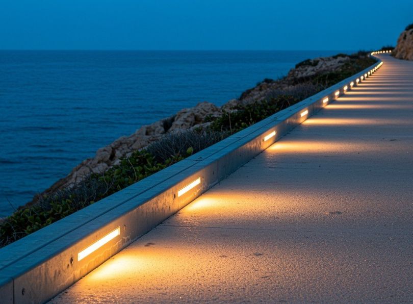
Coastal environments present one of the most formidable challenges for architectural and lighting aluminum profiles. The relentless combination of salt spray, high humidity, UV radiation, and wind accelerates degradation mechanisms unseen in inland settings. For engineers and architects, selecting the correct corrosion resistant profile is not a matter of preference but a critical determinant of project longevity, safety, and lifecycle cost.
This articles delves beyond superficial marketing claims, dissecting the metallurgical properties, protective technologies, and engineering choice required for aluminum profiles to thrive where sea meets land. We answer foundational questions like “What do you mean by corrosion?” and “Which is more resistant to corrosion?”, providing the empirical data and case studies needed for flawless specification.
In this article…
- Corrosion resistant profile: more than just rust
- The aluminum corrosion mechanism in coastal settings
- Alloy selection: the foundation of corrosion resistance
- Protective finishes and surface treatments
- Design and engineering considerations for profiles
- Testing standards and performance data
- Real-world case studies and failure analyses
- Specification guide and selection checklist
- Installation and maintenance protocols
- Future trends in corrosion resistant materials
- Corrosion resistant profiles: the definitive choice for coastal durability
Corrosion resistant profile: more than just rust
The electrochemical basis of corrosion
At its core, corrosion is an electrochemical cell comprising four essential components: an anode (where oxidation occurs, losing electrons), a cathode (where reduction occurs, gaining electrons), an electrolyte (a conductive solution, like saltwater), and a metallic path connecting them. In coastal aluminum, the electrolyte is the thin film of salt-laden moisture on the surface. The anodic and cathodic sites can be microscopic, driven by differences in alloy composition, residual stresses, or surface conditions.
The flow of ions completes the circuit, leading to metal loss at the anode. The rate of this process in a coastal zone is exponentially higher than inland due to the chloride ion’s (Cl⁻) role in breaking down aluminum’s protective oxide layer.
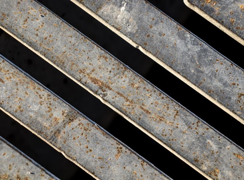
Types of corrosion relevant to coastal aluminum profiles
Understanding what is a corrosion resistant profile requires knowing what it resists. The primary modes include:
Pitting corrosion
The most prevalent and dangerous form for aluminum in chloride environments. It begins with local breakdown of the passive film, creating a small anode. The pit becomes acidic and chloride-rich, accelerating penetration while the large surrounding area acts as the cathode. Pits can be deep and narrow, significantly reducing load-bearing capacity with minimal visible metal loss.
Galvanic (bimetallic) corrosion
Occurs when aluminum is electrically connected to a more noble metal (like stainless steel, copper, or carbon steel) in the presence of an electrolyte. Aluminum, being more anodic, corrodes sacrificially. Coastal moisture provides the perfect electrolyte. This is a leading cause of premature failure in poorly specified assemblies using mixed metals.
Crevice corrosion
Occurs in shielded areas (under gaskets, lap joints, bolt heads) where oxygen diffusion is limited. The differential aeration cell leads to aggressive localized attack. Profile design is critical to prevent crevices.
Filiform corrosion
Appears as thread-like filaments under organic coatings, starting at coating defects. It’s common in painted aluminum exposed to high humidity and salts.
Exfoliation and intergranular corrosion
More related to specific alloy tempers, where corrosion proceeds along grain boundaries, causing the metal to delaminate or lose strength.
The role of chloride ions in accelerating corrosion
Chloride ions (Cl⁻) are small, highly mobile, and aggressive. They competitively absorb into the aluminum oxide surface, displacing oxygen and forming soluble aluminum chloride complexes. This prevents the reformation of the stable oxide layer, allowing the pit to propagate. The concentration of chloride in sea spray can be 10-100 times higher than in urban atmospheres, directly correlating with corrosion rates. Studies show a logarithmic relationship between chloride deposition rate and aluminum corrosion mass loss.
| Environment type | Typical chloride deposition rate (mg/m²/day) | Average aluminum corrosion rate (µm/year) | Relative severity index (1-10) |
|---|---|---|---|
| Rural inland | < 5 | 0.1 – 0.5 | 1 |
| Urban/industrial | 5 – 30 | 0.5 – 2.0 | 3 |
| Coastal (1-5 km inland) | 30 – 150 | 2.0 – 10.0 | 6 |
| Surf zone (< 50m from shore) | 150 – 2000+ | 10.0 – 50.0+ | 9-10 |
| Offshore/marine | > 2000 (immersion/splash) | 50.0 – 200.0+ | 10+ |
The aluminum corrosion mechanism in coastal settings
Breakage of the passive film
The initial attack. Chloride ions penetrate microscopic flaws or impurities in the Al₂O₃ layer. Under humid conditions, they form hydrochloric acid locally, dissolving the oxide. Once the bare aluminum metal is exposed, an anodic site is established. The reaction is:
Al → Al³⁺ + 3e⁻. The electrons released flow to a nearby cathodic site, where oxygen reduction occurs: O₂ + 2H₂O + 4e⁻ → 4OH⁻.
Pit initiation and autocatalytic growth
Inside the developing pit, hydrolysis of Al³⁺ ions generates protons (H⁺), making the solution highly acidic (pH can drop to 2-3). This acidity further accelerates dissolution and prevents repassivation. Chloride ions migrate into the pit to maintain charge neutrality, forming aluminum chloride, which hydrolyzes again, creating a self-sustaining, autocatalytic cycle. The pit growth rate can be orders of magnitude faster than the general surface corrosion rate.
Macrocell formation and profile damage
As pits grow, they become stable macro-anodes. The large, passive surface of the profile acts as the cathode. This large cathode/small anode area ratio is particularly dangerous, concentrating all anodic current into a tiny area, leading to deep, penetrating pits that compromise structural integrity long before significant overall thickness is lost.
| Exposure time (ASTM B117) | Observable stage | Typical pit depth range (µm) | Potential structural impact |
|---|---|---|---|
| 0 – 500 hours | Passive film breakdown, micro-pit initiation | 0 – 10 | Negligible (cosmetic) |
| 500 – 2000 hours | Stable pit growth, visible surface pitting | 10 – 100 | Reduction in fatigue life, aesthetic failure |
| 2000 – 5000 hours | Deep pit propagation, potential undercutting | 100 – 500 | Significant loss of cross-section, risk of perforation in thin walls |
| > 5000 hours | Advanced pitting, possible transition to exfoliation | > 500 | Critical structural compromise, failure likely |
The synergistic effect of environmental factors
Corrosion in coastal areas is not just about salt. It’s a synergy:
- UV radiation: degrades organic coatings, increases surface temperature, and can alter oxide layer properties;
- thermal cycling: daily and seasonal expansion/contraction can break corrosion products, open crevices, and introduce new stresses;
- wind: drives salt spray farther inland and increases the rate of wet/dry cycles, which concentrate salts;
- pollution (SO₂): industrial pollution combined with salt creates acidic sulfate-chloride mixtures more aggressive than chlorides alone.
Therefore, a corrosion resistant profile for a coastal industrial port must meet more stringent criteria than one for a clean, windy beach.
Alloy selection: the foundation of corrosion resistance
The role of alloying elements and impurities
Pure aluminum (Series 1xxx) has excellent corrosion resistance but is soft and weak. Alloying increases strength but can introduce electrochemical heterogeneity. Key elements:
- Copper (Cu): dramatically increases strength (e.g., 2xxx & 7xxx series) but creates highly cathodic intermetallic particles (Al₂Cu), making the alloy very prone to pitting and stress corrosion cracking. Generally avoided for unprotected coastal use.
- Manganese (Mn): (3xxx series) improves strength moderately and has minimal impact on corrosion. Used in non-structural applications.
- Silicon (Si): (4xxx series) lowers melting point, used for brazing and welding wire.
- Magnesium (Mg): the key element for marine alloys (5xxx series). It is solid-solution strengthened and forms the benign β-phase (Al₃Mg₂) upon aging. However, if improperly processed, this phase can become anodic and cause sensitization and stress corrosion cracking.
- Magnesium and silicon (Mg + Si): (6xxx series) form the strengthening Mg₂Si precipitate. These alloys offer an excellent balance of strength, extrudability, and good corrosion resistance.
- Zinc (Zn): the primary alloying element in 7xxx series (with Mg & Cu). Very high strength but poor corrosion resistance unless specifically developed as a “marine grade” with low copper and special tempering (e.g., 7075-T73).
Iron (Fe) and silicon (Si) are common impurities that form intermetallic particles (e.g., Al₃Fe, α-Al(Fe,Mn)Si). These particles are often cathodic to the aluminum matrix and can be initiation sites for pitting. High-purity alloys with controlled Fe:Si ratios are more corrosion resistant.
The 6xxx series (Al-Mg-Si): the benchmark for extruded profiles
Alloys like 6061, 6063, and 6082 are the workhorses of the extrusion industry for good reason. They offer an optimal combination of extrudability, mechanical properties, weldability, and corrosion resistance.
6061-T6/T651
Contains ~1.0% Mg, 0.6% Si, 0.28% Cu, 0.2% Cr. The chromium helps control grain structure. It has higher strength than 6063. Its corrosion resistance is good but can be compromised by the small copper content if not properly anodized or coated. Minimum yield strength ~240 MPa.
6063-T5/T6
The “architectural alloy“. Lower strength (~150 MPa yield) but superior surface finish and extrudability. Has lower copper content than 6061, often making it slightly more corrosion resistant in the same condition. Ideal for complex profiles and high-quality anodizing.
6082-T6
Common in Europe, similar to 6061 with slightly different composition (higher Mn, Si). Offers good strength and corrosion resistance.
The 5xxx series (Al-Mg): the marine champions
For the most severe coastal and marine splash/spray zones, the 5xxx series is often specified. With magnesium as the primary alloy (typically 2.5-5.0%), they offer excellent resistance to seawater, high toughness, and good weldability. They are non-heat-treatable, strength comes from solid solution and strain hardening.
5052-H32/H34
A general-purpose marine alloy with good strength and excellent corrosion resistance. Used for boat hulls, marine components.
5083-H321/H116
The premier marine structural alloy. Contains ~4.5% Mg, 0.7% Mn. The H116/H321 tempers are specifically designed to resist exfoliation and stress corrosion cracking. Used in shipbuilding, offshore platforms, and critical coastal infrastructure. Yield strength ~215 MPa.
5754-H111
Another excellent marine alloy with slightly lower Mg content, often used in automotive and marine applications. Good formability and weldability.
Caveat: 5xxx alloys with Mg content above ~3.5% can become sensitized if held at temperatures between 50-200°C for long periods, leading to intergranular corrosion. The H116/H321 tempers are stabilized to prevent this.
Comparative analysis: making the choice
| Alloy & temper | 0.2% Proof strength (MPa) min. | Relative extrudability | Relative corrosion resistance (C0-C5)* | Salt spray time to first pit (h, avg.) | Typical coastal application | Cost index |
|---|---|---|---|---|---|---|
| 6063-T5 | 110 | Excellent | C3 (Good) | 1,200 | Architectural trim, lighting profiles >500m from shore, with coating | 1.0 (Base) |
| 6061-T6 | 240 | Good | C3 (Good) | 1,500 | Structural supports, brackets, railings 200-1000m from shore | 1.2 |
| 6082-T6 | 250 | Good | C3 (Good) | 1,600 | Similar to 6061, common in European projects | 1.2 |
| 5052-H34 | 180 | Fair (Sheet/Plate) | C4 (Very Good) | 3,500+ | Marine fittings, enclosures, moderate spray zone | 1.5 |
| 5083-H116 | 215 | Fair (Plate) | C5 (Excellent) | 5,000+ | Surf zone structures, offshore platforms, seawall lighting, bridges | 2.0 |
| 7075-T73** | 435 | Poor | C4 (Very Good)** | 3,000 | Aerospace-derived applications needing extreme strength/weight | 3.5+ |
C0: poor, C5: excellent (based on industry classification). Special temper for corrosion resistance; standard T6 is C1 (poor).
Protective finishes and surface treatments
Anodizing: the electrochemical oxide enhancement
Anodizing is not a coating but a controlled, electrochemical thickening of the natural aluminum oxide layer. The aluminum profile acts as the anode in an acidic electrolyte bath (typically sulfuric, chromic, or phosphoric acid). Applying a direct current drives oxygen ions to react with the aluminum surface, building a highly ordered, porous aluminum oxide (Al₂O₃) layer that is integral to the substrate—it cannot peel or flake. This layer is initially porous, which allows for dyeing, but must be sealed to achieve full corrosion resistance. The thickness, density, and quality of this oxide layer are the primary determinants of performance.
Sulfuric acid anodizing (type II)
This is the most common industrial anodizing process. It produces clear or colored coatings typically between 5-25 µm (0.2-1.0 mil) thick. For coastal applications, a minimum thickness of 15-20 µm is strongly recommended. The process offers good abrasion resistance and excellent UV stability (the oxide is inorganic and will not chalk or fade). However, its effectiveness in coastal environments is highly dependent on sealing quality. The porous structure can wick chloride ions if not perfectly sealed, leading to underlying pitting.
Hardcoat anodizing (type III)
Conducted at lower temperatures and higher current densities, this process produces a much harder, thicker (25-100+ µm, or 1-4 mils), and denser oxide layer. Its extreme surface hardness (can exceed 60 Rockwell C) offers superior abrasion and erosion resistance from wind-blown sand—a common issue in coastal areas. The greater thickness provides a longer diffusion path for aggressive ions, significantly enhancing barrier protection. Hardcoat is the anodizing of choice for critical coastal components subject to mechanical wear. It is typically left its natural dark gray or black color.
Sealing processes: locking in the protection
The final, critical step that converts the porous oxide into a truly corrosion resistant barrier. Methods include:
- hot water/steam sealing: hydrates the oxide, causing it to swell and close the pores. Effective but can reduce abrasion resistance slightly.
- nickel acetate sealing: impregnates the pores with nickel salts, offering superior corrosion and stain resistance, especially beneficial for coastal atmospheres. It is often specified for architectural applications.
- mid-temperature sealing: uses organic additives, offering a good balance of performance and energy efficiency.
- cold sealing: a room-temperature process using fluoride-based chemistry; requires careful quality control to ensure effectiveness.
Seal quality is verified by dye absorption tests (e.g., ASTM B136). For coastal projects, specify a nickel acetate or equivalent high-performance seal.
| Anodizing type & specification | Typical thickness (µm) | Seal type | Hours to first visible corrosion | Estimated service life in moderate coastal zone | Key limitation for coastal use |
|---|---|---|---|---|---|
| Decorative (Type II), thin | 5-10 | Hot water | 300-500 | 5-10 years | Insufficient barrier, pitting initiates quickly |
| Architectural (Type II), standard | 15-20 | Hot water | 750-1000 | 15-20 years | Porous layer susceptible to chloride ingress if damaged |
| Architectural (Type II), enhanced | 20-25 | Nickel acetate | 1000-1500 | 20-25+ years | Good overall, but vulnerable to abrasive sand erosion |
| Hardcoat (Type III) | 50 | Nickel acetate | 2000+ | 30-40+ years | Higher cost, color limitations |
| Hardcoat (Type III) | 75-100 | Proprietary/enhanced | 3000+ | 40+ years (potentially) | Significant cost premium, processing limitations |
Results are indicative and depend on alloy, process control, and test interpretation. Estimate based on correlation factors; actual life depends on microenvironment.
Organic coatings (powder & wet paint)
These systems provide a thick, continuous polymeric barrier that physically isolates the aluminum from the environment. They offer superior color and aesthetic flexibility compared to anodizing. The performance is a triad: pretreatment + primer + topcoat. Failure in any one leads to system failure.
Pretreatment: the critical, invisible foundation
This chemical conversion layer promotes coating adhesion and provides secondary corrosion resistance at scratches (inhibition).
- Chromate conversion (yellow/green iridite): historically the gold standard, offering excellent self-healing properties due to hexavalent chromium. Now heavily restricted (RoHS, REACH) due to toxicity. Generally not permissible for new specifications in the EU and many other regions.
- Chrome-free pretreatments (zirconium/titanium based): the modern alternative. Form thin, nanometric oxide layers. Performance has advanced significantly and, when combined with a good primer, can meet the demands of coastal environments. Specify products with proven salt-spray resistance data.
- Phosphoric acid anodizing (PAA): an electrochemical pretreatment (not a final finish) that creates a porous oxide structure ideal for epoxy primer adhesion. Used in high-performance aerospace and marine applications.
Powder coating technologies
Electrostatically applied dry powder, then cured under heat to form a continuous film. Key chemistries for coastal use:
- Polyester (TGIC or TGIC-Free): standard workhorse. Good mechanical properties and color retention. For coastal areas, “superdurable” or “hyperdurable” polyesters with enhanced UV blockers and stabilizers are the minimum recommendation. They resist chalking and gloss loss longer.
- PVDF (polyvinylidene fluoride, e.g., Kynar 500®/Hylar 5000®): the premium architectural standard. Contains ~70% PVDF resin. Exceptionally resistant to UV degradation, chalking, and chemical attack. Color and gloss retention over decades in full sun and salt air is unparalleled among organic coatings. Minimum recommended film thickness: 60-80 µm total system.
- Epoxy: excellent adhesion and chemical resistance but very poor UV resistance (chalk and degrade rapidly). Used almost exclusively as a primer under a UV-resistant topcoat in duplex systems.
Wet spray and fluoropolymer coatings
Liquid coatings applied by spray. Used for complex assemblies that can’t be powder coated, for very thick films, or for specific high-end architectural specs like 100% fluoropolymer systems (e.g., FEVE resins). These offer the ultimate weatherability but at a very high cost.
| Coating system | Typical total dry film thickness (DFT, µm) | Qualitative salt spray resistance (ASTM B117) | UV & chalk resistance (florida exposure) | Best for (coastal context) | Cost index (relative) |
|---|---|---|---|---|---|
| Standard polyester powder | 60-80 | Good (1000-1500h) | Moderate (5-10 yrs before noticeable chalking) | Low-risk residential, >1km from shore | 1.0 |
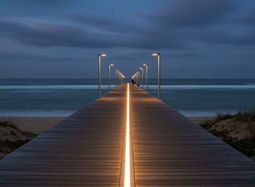
| Superdurable polyester powder | 70-90 | Very good (1500-2000h) | Good (10-15+ yrs) | Most commercial coastal projects, boardwalks, facades | 1.3 |
| PVDF (70%) liquid or powder | 60-80 (min 40 topcoat) | Excellent (2000-3000h+) | Exceptional (20-30+ yrs) | Severe marine exposure, iconic architecture, splash zones | 2.0 – 3.0 |
| Epoxy primer + polyester topcoat (duplex) | 80-120 | Excellent (2000h+) | Depends on topcoat (see above) | High humidity interior or fully sheltered exterior | 1.5 |
| 100% Fluoropolymer (FEVE) liquid | 80-120 | Outstanding (3000h+) | Theoretical >50 yrs | Landmark structures with unlimited budget | 5.0+ |
Combined systems: anodizing + coating (duplex systems)
For maximum protection in the most aggressive splash zones or where both abrasion resistance and color are needed, a duplex system is employed. The profile is first hardcoat anodized (typically 25-50 µm) to provide a stable, abrasion-resistant base with excellent adhesion. Then, a thin (25-50 µm) PVDF or fluoropolymer coating is applied. This combines the corrosion resistant and hard base of anodizing with the color and added barrier of the polymer. If the coating is scratched, the anodic layer protects the substrate, preventing rapid underfilm corrosion. This is considered a “belt and suspenders” approach for critical infrastructure like bridges, offshore platforms, and pier lighting.
Latest innovations: nano-coatings and self-healing layers
Research is pushing beyond traditional methods:
• Sol-gel coatings: inorganic-organic hybrid networks applied as thin films (<5 µm) with excellent adhesion and barrier properties. Often chrome-free.
• Graphene-enhanced coatings: adding small amounts of graphene or graphene oxide to primers creates a more tortuous path for corrosive agents, enhancing barrier properties significantly.
• Self-healing polymers: coatings containing microcapsules of corrosion inhibitors (e.g., cerium, vanadate) or healing agents that rupture upon scratch formation, releasing compounds that actively passivate the exposed aluminum or “heal” the polymer matrix.
While promising, most are in developmental or early commercial stages. For current critical projects, rely on proven systems (PVDF, hardcoat) with long-term exposure track records.
Design and engineering considerations for profiles
Drainage and water management
There are some rules to attend to have the best installation in a corrosive environment, let’s see which ones.
- Rule #1: never trap water: standing water concentrates pollutants and chlorides, creating a perpetual electrolyte.
- Design profiles with a slope: a minimum of 3° is recommended for horizontal surfaces.
- Incorporate drainage holes: in hollow extrusions, include weep holes (Ø ≥ 5mm) at the lowest points to allow condensate and ingress water to escape. Protect holes with mesh to prevent insect nesting.
- Avoid horizontal ledges and pockets: design sections so that all surfaces drain freely. Use canted or rounded surfaces instead of flat ones.
Joint and connection design
Joints are high-risk areas for crevice corrosion and galvanic attack.
- Butt joints vs. lap joints: whenever possible, use welded or gasketed butt joints. Lap joints create a long, narrow crevice. If a lap joint is unavoidable, seal the entire seam with a durable, flexible sealant (e.g., silicone, polysulfide) and consider using a tape separator.
- Fastener selection and isolation: use fasteners of a compatible or more noble material. For aluminum profiles, A2/A4 (304/316) stainless steel is standard: hHowever, even 316 can cause galvanic corrosion in tight, wet crevices. Isolate all fasteners: use nylon or plastic washers, sleeves, and grommets to break electrical contact and prevent crevice formation. Apply a dab of sealant over installed fastener heads.
Crevice elimination
Crevices as small as 25 µm can initiate corrosion. Design strategies can be:
- use continuous welds instead of spot welds or mechanical fasteners where possible;
- for assembled corners, design a drained and ventilated joint, or completely fill it with a structural adhesive/sealant;
- ensure gaskets are compressed, not creating a gap, and are made of non-absorbent, non-leaching material.
Galvanic isolation in multi-metal assemblies
When aluminum profiles must interface with other materials (steel supports, copper busbars) it’s important:
- insulate: use non-conductive spacers, shims, and gaskets (e.g., neoprene, EPDM, plastic);
- coat the more noble material: if isolating isn’t fully possible, coating the cathode (e.g., painting the steel support) reduces the effective cathode area, slowing the galvanic reaction;
- avoid direct earth/ground connections: where stray currents are possible, ensure electrical isolation from grounding systems.
Thermal break design in coastal curtain walls
For fenestration profiles, thermal breaks are essential for energy efficiency but introduce a potential weakness. The polyamide strip must be perfectly bonded to the aluminum. Any breach allows saltwater into the joint between the inner and outer aluminum, leading to concealed corrosion. Choose thermal break systems from reputable manufacturers with proven long-term performance data in marine environments and robust warranties.
Testing standards and performance data
Accelerated laboratory tests
Neutral salt spray (fog) test – ASTM B117 / ISO 9227
The most common test. Samples are exposed to a continuous fog of 5% NaCl solution at 35°C. It’s a comparative test, not a predictor of exact service life. Results are reported as hours to first white corrosion (oxide), red rust (on fasteners), or blistering. For coastal profiles, a minimum of 1000-1500 hours without failure on the face is a common baseline. PVDF systems often exceed 3000 hours.
Cyclic corrosion tests (CCT)
More realistic than continuous salt spray. They simulate wet/dry cycles, UV exposure, and sometimes freeze/thaw. Examples:
- ASTM G85, Annex A5 (Prohesion™): alternating cycles of salt fog and dry-off at lower temperatures. Often better correlates with industrial/coastal atmospheric corrosion.
- ISO 12944-6 CX Cycles: defines test regimes for different corrosivity categories (C2-C5). For coastal (C5-M), tests include salt spray, humidity, and drying phases over a 4200-hour cycle.
- ASTM D5894 (UV/Salt Fog/Cold Cycle): combines QUV weathering with salt spray, excellent for evaluating organic coatings.
Filiform corrosion test – ASTM D2803 / ISO 4623
Evaluates the susceptibility of coated aluminum to thread-like corrosion under the coating from a scribe. Critical for painted aluminum in humid environments.
Electrochemical impedance spectroscopy (EIS)
Advanced, non-destructive test that measures the electrical resistance and capacitance of a coating system. A high impedance value indicates a good, intact barrier. It can detect early-stage degradation long before it’s visible.
Real-world exposure and correlation
Laboratory tests provide acceleration factors (AF). For example, 1000 hours in ASTM B117 might correlate to ~5-10 years in a moderate coastal (C4) environment, but the AF varies widely based on exact location. Always prefer suppliers who can provide real-world exposure data from coastal test racks (e.g., at Kure Beach, NC; Biscay Bay, France; or Miyakojima, Japan). This is the most reliable performance indicator.
| Corrosivity category (atmosphere) | Description (typical coastal environment) | Expected coating durability | Typical test validation requirement |
|---|---|---|---|
| C3 medium | Urban/coastal areas with low chloride deposition (>5km inland) | >15 years | 1440h Salt Spray (ISO 9227) or equivalent CCT |
| C4 high | Coastal areas with moderate salt load (500m – 5km inland) | >15 years | 2000-3000h of relevant CCT (e.g., ISO 12944-6 CX cycle) |
| C5-M very high (marine) | Coastal/offshore with high salinity and frequent condensation (<500m from shore, splash zone) | >25 years (Very High) | >4200h of severe CCT or proven real-world exposure data |
Real-world case studies and failure analyses
Case study: mediterranean boardwalk lighting system (failure)
Project: a 2km-long seaside promenade lighting system, Southern France.
Specification (original): extruded profiles in alloy 6063-T5, finished with a 10 µm clear anodizing (decorative grade) to maintain a metallic appearance. Fasteners: zinc-plated steel.
Failure mode & timeline: within 18 months, white corrosion staining appeared around fastener points and on horizontal surfaces. By year 3, significant pitting and aesthetic degradation were evident on many posts. Several luminaires developed electrical faults due to corroded grounding connections.
Root cause analysis:
- Inadequate alloy/finish: 6063-T5 has good resistance, but the 10 µm anodizing was too thin for the severe marine C5 environment. It provided minimal barrier.
- Galvanic corrosion: zinc-plated steel fasteners are highly anodic to aluminum. The plating corroded rapidly, and once depleted, the underlying steel rusted, creating voluminous corrosion products that cracked the anodizing and accelerated aluminum pitting.
- Design flaws: flat-top profile caps trapped rainwater, which became concentrated with salt.
Cost of failure: complete system replacement after 5 years at 300% of the original budget, plus reputational damage.
Corrected specification (retrofit): profiles in 6082-T6 alloy with a 25 µm architectural anodizing (sealed with nickel acetate) or a 80 µm superdurable polyester powder coat. Fasteners changed to A4 (316) stainless steel with nylon isolation washers. Redesigned profiles with sloped tops and drainage holes.
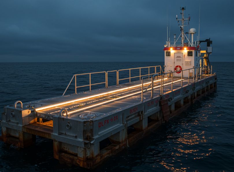
Case study: north sea offshore monitoring platform
Project: unmanned meteorological and sea-state monitoring platform 15km offshore in the North Sea.
Specification: structural framework and enclosures fabricated from 5083-H116 marine grade aluminum plate and extrusions. All exposed surfaces received a chrome-free zirconium pretreatment, followed by a 120 µm total DFT coating system: 60 µm epoxy primer + 60 µm PVDF (70%) topcoat in RAL 7016. Fasteners: A4 (316) stainless steel, isolated with plastic caps and Duralac insulating compound at all contact points. All seams welded and sealed.
Performance: after 10 years of continuous exposure in a C5-M offshore environment (high wind, constant salt spray, UV), the platform was inspected.
Findings: coating showed minimal chalking (gloss retention >85%). No blisters, delamination, or corrosion creep from the few minor impact scars. Fasteners showed no signs of galling or crevice corrosion. The aluminum substrate was pristine where the coating was intact.
Key success factors:
- correct alloy choice (5083) for the most severe environment.
- a high-performance, high-thickness coating system specified for the correct service life (>25 years).
- meticulous attention to galvanic isolation at every connection point.
- rigorous factory application control and inspection before deployment.
Lifecycle cost: high initial investment, but zero maintenance costs to date, with an predicted service life exceeding 40 years, demonstrating excellent lifetime value.
Specification guide and selection checklist
Step 1: define the environmental severity.
- Determine distance from coastline, elevation, prevailing wind direction, and presence of industrial pollution.
- Assign a standardized corrosivity category (e.g., ISO 12944 C4 or C5-M).
Step 2: select the base alloy.
- C3/C4 moderate-severe: 6061-T6, 6082-T6 (with robust finish).
- C5-M very severe/splash zone: 5083-H116/H321, 5754.
- Require mill certificates for alloy and temper.
Step 3: specify the surface treatment system.
- Anodizing path: minimum 20 µm architectural (Type II) with nickel acetate seal for C4; 50+ µm hardcoat (Type III) for C5-M.
- Coating path: minimum Superdurable Polyester (70-90 µm) for C4; PVDF system (60-80 µm min.) for C5-M. Specify pretreatment: chrome-free Zr/Ti type.
- Duplex system: for ultimate protection: Hardcoat anodize (25-50 µm) + PVDF coating (25-50 µm).
- Specify required test performance (e.g., “Coating system shall achieve >2000 hours in ASTM B117 with no blistering or corrosion on face”).
Step 4: design and detailing.
- Review profile cross-sections: ensure slopes, drainage, no water traps.
- Detail joints for sealing or drainage.
- Specify fastener material (A2/A4 stainless) and mandate isolation (washers, sleeves, gaskets).
- Prohibit direct contact with dissimilar metals (copper, carbon steel, untreated zinc).
Step 5: quality assurance and documentation.
- Require third-party coating inspector (e.g., FROSIO, NACE certified) for application.
- Require documentation of dry film thickness (DFT) readings, adhesion tests (ASTM D3359), and salt spray test reports on production panels.
- Specify packaging to prevent transit damage to finishes.
At this point: what type of profile need on cost environment? The answer is in a profile defined by a marine-grade or high-purity 6xxx alloy, with a rigorously applied and thick anodic layer or high-performance polymer coating, designed without water traps, and specified with compatible, isolated fasteners. For a costal (coastal) environment, never compromise on alloy, finish thickness, or isolation details.
Installation and maintenance protocols
Handling & storage: store profiles off the ground, under cover, and away from contaminating materials (e.g., fertilizer, road salt). Use nylon slings for lifting, avoid steel chains or cables that can gouge the finish.
Installation:
- use tools with non-metallic jaws to prevent scratching.
- if field cutting is necessary, protect the cut ends. For anodized profiles, touch up with a clear, UV-resistant chromate-free aluminum paint. For coated profiles, use a two-part epoxy touch-up paint specified by the coating manufacturer.
- apply sealants as per design, ensuring surfaces are clean and dry.
- torque fasteners correctly—overtightening can crush isolation washers and distort profiles, creating crevices.
Maintenance: even the best systems benefit from simple maintenance.
- Annual inspection: check for physical damage, coating scratches, sealant integrity, and any signs of corrosion at joints or fasteners.
- Cleaning: rinse with fresh water periodically (especially after storms) to remove salt deposits. Use a mild, pH-neutral detergent with a soft brush or cloth. Avoid abrasive cleaners, steel wool, or high-pressure washers that can damage the finish.
- Repair: address minor scratches immediately with manufacturer-approved touch-up kits. For significant damage, consider section replacement.
Future trends in corrosion resistant materials
- Additive manufacturing (3D printing) of aluminum: allows for complex, optimized geometries that are impossible to extrude, potentially creating internal structures that minimize material use while maximizing strength and natural drainage. Challenges include achieving the same alloy density and corrosion properties as wrought material.
- New alloy developments: research into aluminum-magnesium-scandium (Al-Mg-Sc) alloys promises higher strength and potentially better corrosion performance than standard 5xxx series. Nanostructuring of alloys to create more homogeneous microstructures is another frontier.
- Smart coatings and sensors: coatings embedded with pH-sensitive pigments that change color when corrosion initiates, allowing for visual early warning. Micro-sensors embedded in profiles could wirelessly transmit data on coating impedance, alerting to the need for maintenance before failure is visible.
- Bio-inspired and self-healing systems: beyond microcapsules, research into vascular networks within coatings (like human skin) that can deliver healing agents repeatedly to damage sites. Surfaces engineered at the nanoscale to mimic the lotus leaf, creating super-hydrophobic surfaces that repel water and salt.
- Sustainability-driven changes: increased use of recycled aluminum (with tight control over tramp elements like copper and iron that harm corrosion resistance). Development of even more robust chrome-free pretreatments and low-VOC, bio-based coating resins.
Corrosion resistant profiles: the definitive choice for coastal durability
Specifying corrosion resistant aluminum profiles for coastal applications demands a 360° approach. There is no single “best” answer, but a series of informed compromises between strength, cost, durability, and aesthetics. The core principles derived from this comprehensive analysis are:
- match the alloy to the severity of exposure: 5xxx series for severe/splash zones, 6xxx series for moderate coastal with appropriate finishing;
- never rely on bare aluminum: specify a robust, quality-controlled surface treatment (thick anodizing with proper sealing or high-performance coating systems like PVDF) validated for the specific environment;
- design with corrosion prevention in mind: eliminate crevices, ensure positive drainage, and meticulously avoid galvanic couples through isolation and compatible material selection;
- validate with relevant accelerated testing: demand supplier quality certifications and performance data (ASTM B117, cyclic tests) that correlate to your project’s corrosivity category;
- install and maintain with an understanding of the protection system’s limits: proper handling, use of isolation details, and periodic fresh-water rinsing are essential to achieve the designed service life.
By adhering to these principles and utilizing the detailed data and case studies provided herein, engineers and designers can move beyond guesswork. They can make confident, defensible specifications that ensure aluminum profiles deliver on their promise of lightweight, durable, and sustainable performance, standing resilient against the relentless challenge of the coastal frontier for decades to come. The investment in correct specification upfront pays manifold dividends in reduced lifecycle costs, structural integrity, and architectural legacy.